


Instruction Manual
IB-106-300NH Rev. 4.3
May 2005
Rosemount Analytical Inc. A Division of Emerson Process Management Installation 2-7
World Class 3000
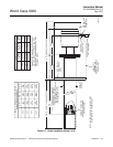
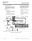
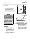
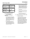
4. If using the optional ceramic diffusor
element, the vee deflector must be cor-
rectly oriented. Before inserting the
probe, check the direction of flow of the
gas in the duct. Orient the vee deflector
on the probe so that the apex points
upstream toward the flow (Figure 2-2).
This may be done by loosening the
setscrews, and rotating the vee de-
flector to the desired position.
Retighten the setscrews.
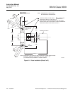
5. In horizontal installations, the probe
junction box should be oriented so that
the system cable drops vertically from
the probe junction box. In a vertical in-
stallation, the system cable can be ori-
ented in any direction.
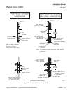
6. If the system has an abrasive shield,
check the dust seal packings. The
joints in the two packings must be
staggered 180°. Also, make sure that
the packings are in the hub grooves as
the probe slides into the 15° forcing
cone in the abrasive shield.
NOTE
If process temperatures will exceed
392°F (200°C), use anti-seize com-
pound on stud threads to ease future
removal of probe.
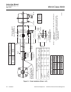
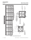
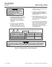
7. Insert probe through the opening in the
mounting flange and bolt the unit to the
flange. When probe lengths selected
are 9 or 12 ft (2.75 or 3.66 m), special
brackets are supplied to provide addi-
tional support for the probe inside the
flue or stack. See Figure 2-1, sheet 5.
NOTE
Probe Installation
To maintain CE compliance, ensure
there is a good connection between
the chassis of the probe and earth.
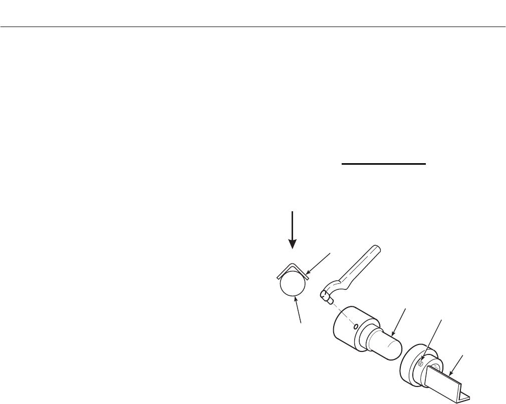
VEE
DEFLECTOR
VEE
DEFLECTOR
DIFFUSION
ELEMENT
SETSCREW
FILTER
GAS FLOW
DIRECTION
APEX
624017
Figure 2-2. Orienting the Optional Vee Deflector