


⎯ 75 ⎯
6 F 2 S 0 8 5 7
3.4 Recording Function
GRT100 is provided with the following recording functions:
Fault recording
Event recording
Disturbance recording
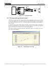
These records are displayed on the LCD of the relay front panel or on the local or remote PC.
3.4.1 Fault Recording
Fault recording is started by a tripping command of the GRT100 or PLC command by user-setting
(max. 8) and the following items are recorded for one fault:
Date and time of fault occurrence
Operating phase or fault phase
Tripping command
Tripping mode
Power system quantities
Up to the 8 most-recent faults can be stored as fault records. If a new fault occurs when 8 faults
have been stored, the record of the oldest fault is deleted and the record of the latest fault is then
stored.
Date and time of fault occurrence
The time resolution is 1ms using the relay internal clock.
To be precise, this is the time at which a tripping command has been initiated, and thus it is
approximately 10 ms after the occurrence of the fault.
Operating phase or fault phase
The operating phase or fault phase can be selected to be displayed following tripping, depending
on the requirements of user.
For details, see Section 2.3.1.
Tripping command
The tripping output relay(s) operated is shown in terms of its number (e.g. TP-1: 1, TP-2: 2 etc.).
Tripping mode
This shows the protection scheme that initiated the tripping command.
Power system quantities
The following power system quantities for pre-fault and post-fault are recorded.
- Magnitude and phase angle of phase current of each winding (I
a1
, I
b1
, I
c1
up to I
a3
, I
b3
, I
c3
)
- Magnitude and phase angle of neutral current of each winding (I
n1
up to I
n3
)
- Magnitude and phase angle of symmetrical component current of each winding (I
11
, I
21
, I
01
up to I
13
, I
23
, I
03
)
- Magnitude and phase angle of phase-to-phase voltage (V)