


⎯ 14 ⎯
6 F 2 S 0 8 5 7
Display mode following differential tripping
Following a trip output, GRT100 can display either the operating phase or the faulted phase
according to the user’s requirements as shown in Table 2.2.1.1. The operating phase or faulted
phase display is selectable by a setting in the Record menu.
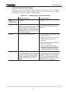
Table 2.2.1.1 Operating Phase / Faulted Phase Display
Operating phase display Faulted phase display
Setting
(Setting/Record/Fault
record/Phase mode)
1 = Operating 2 = Fault
Displayed phase Operating phase
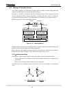
Generally, the operating phase of the DIF element
does not correspond with the faulted phase, but
depends on the transformer configuration and the
electrical quantities that are input to the GRT100
current differential calculation.
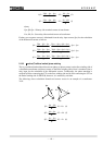
Faulted phase (for single-phase to earth, phase to
phase, two-phase to earth and three-phase to
earth faults)
Application All two- and three-winding transformers
• Faults at primary side or secondary side of Yy0
and Yy6 transformers
• Faults at primary side of Yd1, Yd3, Yd5, Yd7,
Yd9, Yd11, Yy2, Yy4, Yy8 and Yy10
transformers
• Faults at secondary side of Dy1, Dy3, Dy5, Dy7,
Dy9 and Dy11 transformers
• Faults on Dd2, Dd4, Dd6, Dd8 and Dd10
transformers, faults at Zig-zag connected side
of transformers and faults at tertiary side of
three-winding transformers are not supported.
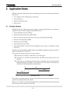
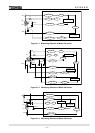
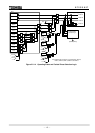
Logic Refer to Figure 2.2.1.4.
∗ Phase (A/B/C) display is based on the operating
signal of DIF or HOC element, and “N” display is
based on the operating signal of REF and DIFT
elements. If the REF is not used, “N” is not
displayed.
Refer to Figure 2.2.1.4.
∗ Phase (A/B/C) display is based on the operating
signal of DIF or HOC element and a differential
current value, and “N” display is based on the
operating signal of REF and DIFT elements. If the
REF is not used, “N” is not displayed.