


⎯ 141 ⎯
6 F 2 S 0 8 5 7
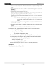
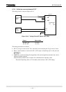
6.5.1.6 Definite time overcurrent elements OC, EF
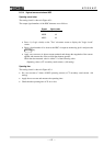
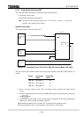
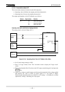
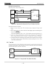
The testing circuit is shown in Figure 6.5.10.
Single-phase
current
source
A
TB1
TB4
-2
-1
-7
-8
-
A
16
-
A
17
E
I
a
I
N
GRT100
DC
power
supply
+
−
Monitoring
j
ack
A
0V
Figure 6.5.10 Testing OC and EF (Model 100s, 200s)
Element Signal number
1OC, 2OC, 3OC 47, 53, 59
1EF, 2EF, 3EF 72, 75, 78
The testing procedure is as follows:
• Press 4 (= Logic circuit) on the "Test" sub-menu screen to display the "Logic circuit" screen.
• Enter a signal number to observe the OC or EF output at monitoring jack A and press the
ENTER
key.
• Apply a test current and change the magnitude of the current applied and measure the value at
which the element operates.
Check that the measured value is within
±5% of the theoretical operating value.
Theoretical operating value = (CT secondary rated current) × (OC or EF setting)