


⎯ 153 ⎯
6 F 2 S 0 8 5 7
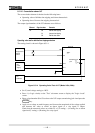
If no message is shown on the LCD, this means that the failure location is either in the DC power
supply circuit or in the microprocessors mounted on the SPM module. Then check the "ALARM"
LED. If it is off, the failure is in the DC power supply circuit. If it is lit, open the relay front panel
and check the LEDs mounted on the SPM module. If the LED is off, the failure is in the DC power
supply circuit. If the LED is lit, the failure is in the microprocessors.
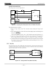
In the former case, check if the correct DC voltage is applied to the relay.
If so, replace the IO1 or IO8 module mounting the DC/DC converter and confirm that the
"ALARM" LED is turned off.
In the latter case, replace the SPM module containing the processors and confirm that the
"ALARM" LED is turned off.
When a failure is detected during regular testing, it will not be difficult to identify the failed
module to be replaced.
Note: When a failure or an abnormality is detected during the regular test, confirm the following
first:
- Test circuit connections are correct.
- Modules are securely inserted in position.
- Correct DC power voltage with correct polarity is applied and connected to the correct
terminals.
- Correct AC inputs are applied and connected to the correct terminals.
- Test procedures comply with those stated in the manual.
6.7.3 Replacing Failed Modules
If the failure is identified to be in the relay module and the user has spare modules, the user can
recover the protection by replacing the failed modules.
Repair at the site should be limited to module replacement. Maintenance at the component level is
not recommended.
Check that the replacement module has an identical module name (VCT, SPM, IO1, IO2, etc.) and
hardware type-form as the removed module. Furthermore, the SPM module should have the same
software name.
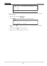
The module name is indicated on the bottom front of the relay case. The hardware type-form is
indicated on the module in the following format:
Module name Hardware type-form
VCT G1PC2-
SPM
G1SP∗-
IO1 G1IO1-
IO2 G1IO2-
IO3 G1IO3-
IO8 G1IO8-
HMI --