


⎯ 29 ⎯
6 F 2 S 0 8 5 7
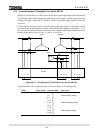
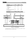
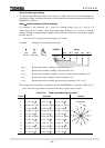
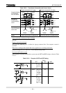
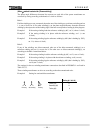
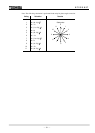
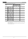
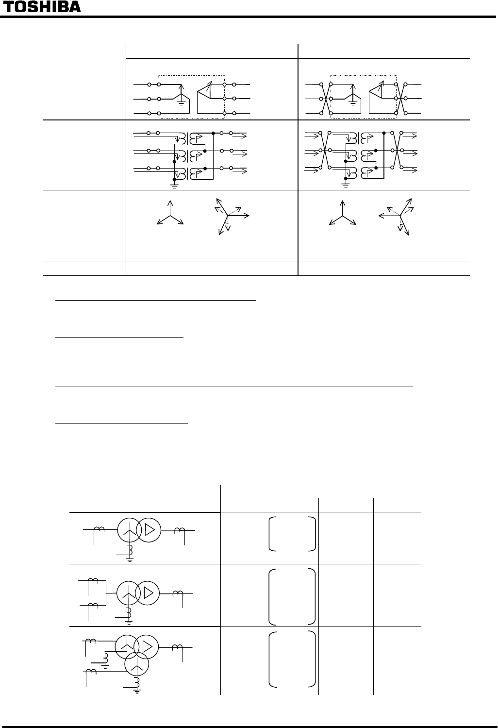
Table 2.2.5.3 Transformer Connection and Current Vector
Delta-side connected with 30° lagging Delta-side connected with 30° leading
Connection between
Yd1 Transformer
and Power system
Yd1
Primary
Secondary
Transformer
u
v
w
U
V
W
a
b
c
a
b
c
Yd1
Primary
Secondary
Transformer
u
v
w
U
V
W
a
b
c
a
b
c
Each winding
connection and
Incoming/Outgoing
current
Transformer
u
v
w
U
V
W
a
b
c
a
b
c
I
1a
I
1b
I
1c
I
2a
I
2b
I
2c
I
2c’
=I
2c
−
I
2b
I
2b’
=I
2b
−
I
2a
I
2a’
=I
2a
−
I
2c
Transformer
u
v
w
U
V
W
a
b
c
a
b
c
I
1a
I
1b
I
1c
I
2c
I
2b
I
2a
I
2c’
=I
2c
−
I
2a
I
2b’
=I
2b
−
I
2c
I
2a’
=I
2a
−
I
2b
I
1c
I
1b
I
1a
Incoming current
vector and Outgoing
current vector
Incoming
Current
Outgoing
Current
I
1a
I
1c
I
1b
I
2b
I
2c
I
2a
I
2b’
=I
2b
−
I
2a
I
2c’
=I
2c
−
I
2b
I
2a’
=I
2a
−
I
2c
30
°
Incoming
Current
Outgoing
Current
I
1a
I
1c
I
1b
I
2b
I
2c
I
2a
I
2c’
=I
2c
−
I
2a
I
2a’
=I
2a
−
I
2b
I
2b’
=I
2b
−
I
2c
30
°
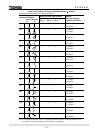
Setting Yd_p=1, yd_s=2, vec_s=1 (Same as Yd1) Yd_p=1, yd_s=2, vec_s=11 (same as Yd11)
Auto-transformer (with internal delta-winding)
Set Yy0.
Zigzag connected transformer
Set yd_p, yd_s and vec_s to 2 (=delta) for zigzag connected side. Zero-sequence current is
canceled.
When three-winding model (model 200 series) applied to two-winding transformer:
Keep the settings of “yd_t” and “vec_t” to the default setting values.
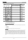
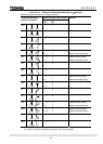
One-and-a-half breaker system
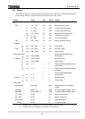
When applied to one-and-a-half breaker system, note the DIFT and REF setting as shown in Table
2.2.5.4.
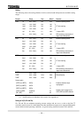
Table 2.2.5.4 Example of DIFT and REF Setting
Setting
DIFT 1REF 2REF
Yd11
Yd11 yd_p=1
yd_s=2
vec_s=11
1I0 --
Yd11
One-and-a-half breaker system
Yy0d11
yd_p=1
yd_s=1
vec_s=0
yd_t=2
vec_s=11
2Io --
Yy0d11
Yy0d11
yd_p=1
yd_s=1
vec_s=0
yd_t=2
vec_s=11
1I0 1I0