


⎯ 22 ⎯
6 F 2 S 0 8 5 7
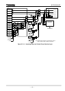
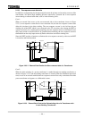
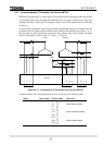
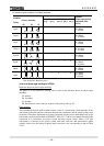
2.2.4 Connection between CT Secondary Circuit and the GRT100
GRT100 is provided with 2 or 3 three-phase current input terminals depending on the relay model.
To validate the phase angle matching described previously and apply in-phase current from each
winding to the relay, connect the CT secondary circuits to the current input terminals of the relay
as follows;
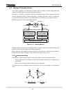
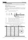
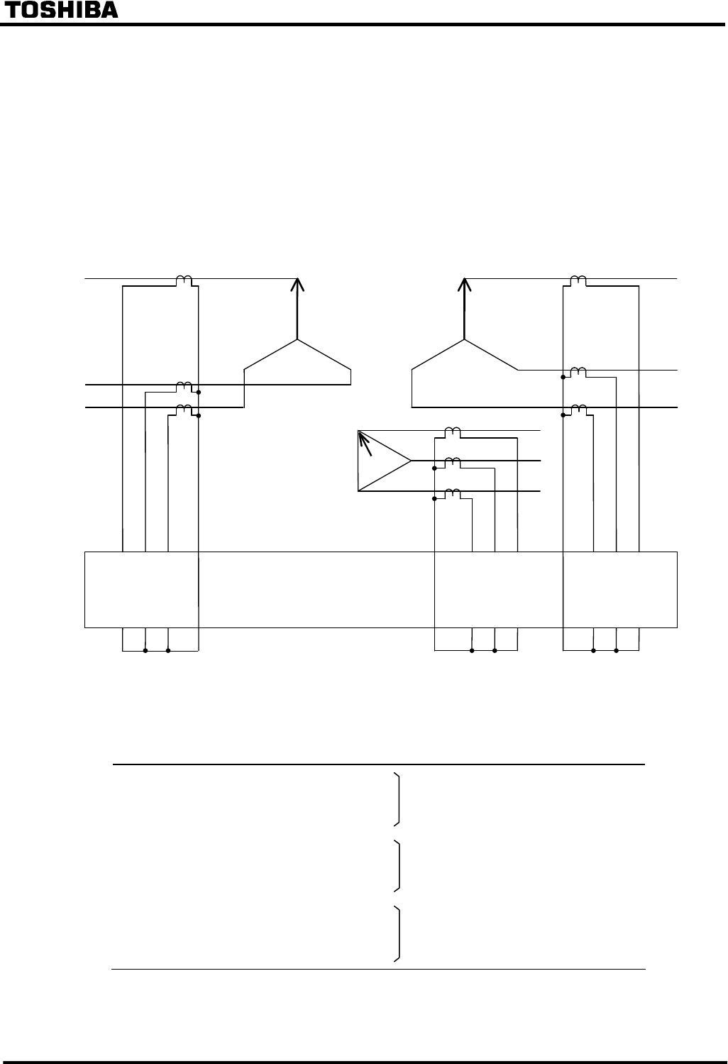
As shown below, the phases used in the phase angle setting (indicated by an arrowhead) must be
connected to the AC input terminals with the lowest number in the terminal group such as 1, 9, 17,
then the other two phases should be connected to the terminals with a larger number clockwise
from the setting phase, such as 3 and 5, 11 and 13, or 19 and 21.
GRT100
Secondary
Primary
3
2 4 6
1 5
9
13
18 10
12
14 20
22
11
17 19
21
Tertiary
Figure 2.2.4.1 Connection of CT Secondary Circuit and the GRT100
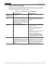
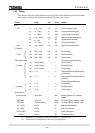
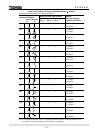
Terminal numbers and corresponding input currents are shown in the following table.
Model Terminal block
Terminal number Input current
100 series / 200 series TB1 1-2
3-4 Current of primary winding
5-6
9-10
11-12 Current of secondary winding
13-14
17-18
19-20 Current of tertiary winding
21-22