


⎯ 268 ⎯
6 F 2 S 0 8 5 7
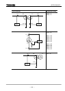
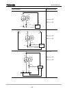
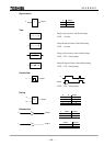
Symbols used in the scheme logic and their meanings are as follows:
Signal names
Marked with : Measuring element output signal
Marked with : Binary signal input from or output to the external equipment
Marked with [ ] : Scheme switch
Marked with " " : Scheme switch position
Unmarked : Internal scheme logic signal
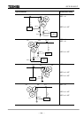
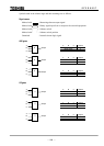
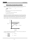
AND gates
A B C Output
1 1 1 1
Other cases 0
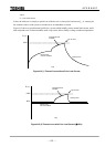
A B C Output
1 1 0 1
Other cases 0
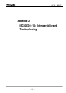
A B C Output
1 0 0 1
Other cases 0
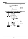
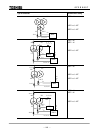
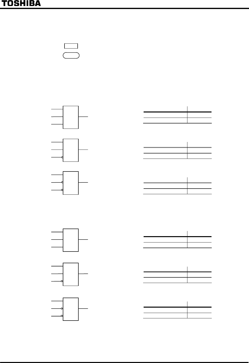
OR gates
A B C Output
0 0 0 0
Other cases 1
A B C Output
0 0 1 0
Other cases 1
A B C Output
0 1 1 0
Other cases 1
A
Output
B &
C
A
Output
B
≥1
C
A
Output
B &
C
A
Output
B
C
A
Output
B
≥1
C
A
Output
B
≥1
C
&