


⎯ 61 ⎯
6 F 2 S 0 8 5 7
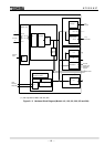
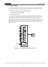
3.1.2 Transformer Module
The transformer module (VCT module) provides isolation between the internal and external
circuits through auxiliary transformers and transforms the magnitude of the AC input signals to
suit the electronic circuits. The AC input signals are as follows:
• three-phase currents (I
a
, I
b
and I
c
) for each winding
• neutral current (I
N
) for each winding
• phase-to-phase voltage
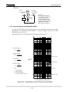
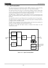
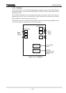
Figure 3.1.4 shows a block diagram of the transformer module. There are 8 to 12 auxiliary CTs
and 1 auxiliary VT mounted in the transformer module depending on the relay model. (For the
correspondence between the relay model and number of AC input signals, see Table 3.2.1.)
The transformer module is also provided with an IRIG-B port. This port collects the serial
IRIG-B format data from an external clock for synchronization of the relay calendar clock. The
IRIG-B port is isolated from the external circuit by a photo-coupler. A BNC connector is used as
the input connector.
I
a1
I
b1
I
c1
I
N1
Signal
processing
module
I
a2
I
b2
I
c2
IRIG-B port
BNC connector
I
N2
External
clock
V
Figure 3.1.4 Transformer Module (e.g. models 101, 102)