


⎯ 65 ⎯
6 F 2 S 0 8 5 7
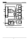
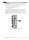
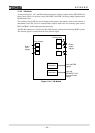
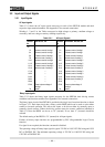
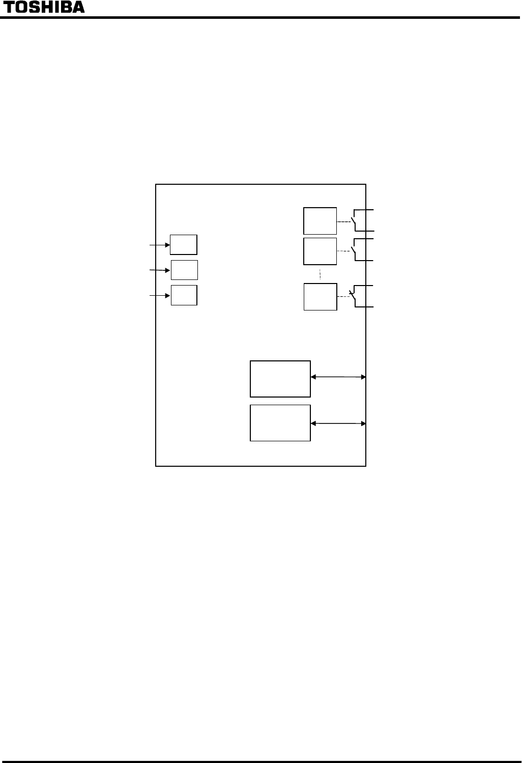
3.1.4.2 IO2 Module
As shown in Figure 3.1.4.3, the IO2 module incorporates 3 photo-coupler circuits (BI14-BI16) for
binary input signals, 14 auxiliary relays (BO1-BO13 and FAIL) for binary output signals and an
RS-485 transceiver.
The auxiliary relay FAIL has one normally closed contact, and operates when a relay failure or
abnormality in the DC circuit is detected. BO1 to BO13 each have one normally open contact.
BO12 and BO13 are the high-speed operation type.
The RS-485 transceiver is used for the link with the relay setting and monitoring (RSM) system.
The external signal is isolated from the relay internal signal.
A
uxiliary relay
RS-485
Transceiver
BI14
BI15
BI16
Binary
output
signals
Binary
input
signals
Photo-coupler
Link with RSM
system
BO2
FAIL
BO1
RS-485
Transceiver
Link with
IEC60870-5-103
Communication
system
Figure 3.1.4.3 IO2 Module