


⎯
327 ⎯
6 F 2 S 0 8 5 7
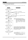
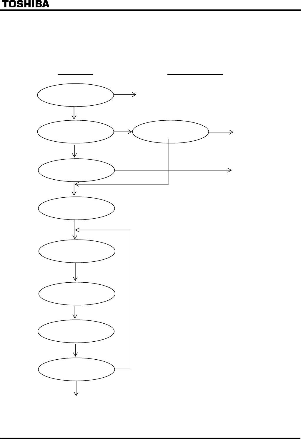
1. Failed module tracing and its replacement
If the “ALARM” LED is ON, the following procedure is recommended. If not repaired, contact
the vendor.
“ALARM” LED ON?
Any LCD messages?
Locate the failed module.
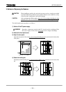
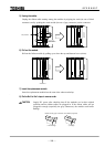
Module re
p
lacement
If both “IN SERVICE” LED and “ALARM” LED are
OFF, check the followings.
Check: Is DC supply voltage available with the correct
polarity and of adequate magnitude, and
connected to the correct terminals?
No
No failure
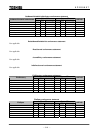
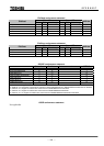
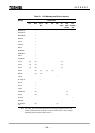
Locate the failed module referring to Table R-1.
Caution: Check that the replacement module has an
identical module name (VCT, SPM, IO1,
IO2, etc.) and hardware type-form as the
failed module. Furthermore, the SPM
module must have the same software
name and version. Refer to Section
4.2.5.1.
Countermeasure
As shown in the table, some of the messages cannot
identify the fault location definitely but suggest plural
possible failure locations. In these cases, the failure
location is identified by replacing the suggested
failed modules with spare modules one by one until
the "ALARM" LED is turned off.
DC su
pp
l
y
“OFF”
DC su
pp
l
y
“ON”
“
A
LARM” LED OFF?
No
Contact the vendor.
End
No
Not displayed
Press [VIEW] key
Contact the vendor.
Not displayed
Press [VIEW] key
Yes
Yes
Procedure