


⎯ 23 ⎯
6 F 2 S 0 8 5 7
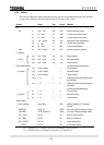
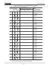
2.2.5 Setting
The following shows the setting elements necessary for the current differential protection and their
setting ranges. Setting can be performed on the LCD screen or PC screen.
Element Range Step Default
Remarks
DIFT
DIF
i
k
0.10 − 1.00
(
∗
)
0.01 0.30 Minimum operating current
p1
10 − 100%
1% 100% % slope of small current region
p2
10 − 200%
1% 200% % slope of large current region
kp
1.00 − 20.00(*)
0.01 1.00 Break point of dual characteristics
k2f
10 − 50%
1% 15% Second harmonic detection
k5f
10 − 100%
1% 30% Fifth harmonic detection
HOC kh
2.00 − 20.00(*)
0.01 2.00 High-set overcurrent protection
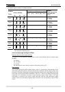
CT matching
kct1
0.05 − 50.00
0.01 1.00 Primary winding
CT ratio kct2
0.05 − 50.00
0.01 1.00 Secondary winding
kct3
0.05 − 50.00
0.01 1.00 Tertiary winding
Phase angle matching
If [Phase matching]=Alpha setting
yd_p 1(star) / 2(delta) 1 Primary winding
(α-method)
yd_s 1(star) / 2(delta) 1 Secondary winding
yd_t 1(star) / 2(delta) 1 Tertiary winding
vec_s 0 – 11 1 0 Phase angle difference between primary
and secondary
vec_t 0 – 11 1 0 Phase angle difference between primary
and tertiary
If [Phase matching]=Beta setting
d1
0 − 11
1 0 Primary winding
(β-method)
d2
0 − 11
1 0 Secondary winding
d3
0 − 11
1 0 Tertiary winding
Scheme switch
[Phase matching] Alpha / Beta Beta Matching methods of CT secondary
currents
[DIFTPMD] 3POR / 1P 3POR Trip mode (if [Phase matching] = Alpha)
[DIFTPMD] 3POR / 2PAND / 1P
3POR Trip mode (if [Phase matching] = Beta)
[2F – LOCK] Off / On On Block by second harmonic
[5F - LOCK] Off / On On Block by fifth harmonic
[DIF1] to [DIF5] Off / On (**) Output tripping signal
[CTSEN] Off / On Off CT saturation function
(∗): Multiplier of CT secondary rated current including CT ratio correction.
(**): Default settings are dependent on the models. See Appendix H.