


⎯ 16 ⎯
6 F 2 S 0 8 5 7
2.2.2 Stability for CT Saturation during Through-fault Conditions
For current differential protection of transformers, GRT100 has a strong restraint characteristic in
the large current region for erroneous differential current due to CT saturation. Further, GRT100
provides a CT saturation countermeasure function. If any CTs saturate due to a large through-fault
current, an apparent differential current is generated in the differential circuit and may cause false
operation of the differential protection.
Operation Principle
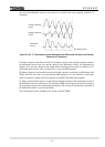
Even when a CT saturates under very large primary currents, the waveform of the saturated CT
secondary current has two identifiable periods in each cycle: a non-saturated period and a
saturated period. The GRT100 utilizes this phenomenon and provides very secure operation for
external faults with a large through-fault current.
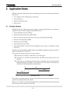
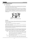
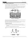
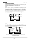
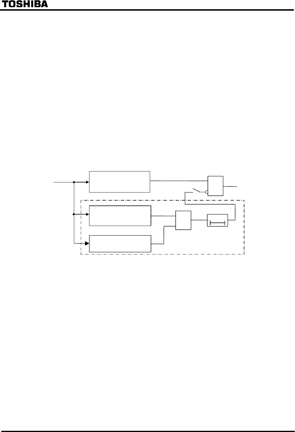
Figure 2.2.2.1 shows a block diagram of the CT saturation countermeasure (CTS). The CTS has a
waveform discriminating element (WDE) and starting element (SE). WDE operates if the change
in the instantaneous value of the differential current is less than a specified percentage of the
change in the instantaneous value of the restraining current. In the CTs non-saturated period, the
differential current is theoretically zero for through-fault currents. The element operates in this
period.
Differential Element
(DIFT_DIF)
&
&
0
t
CTS
Waveform Discriminating
Element
Starting Element
Tripping
Output
Current
Input
[CTSEN]
ON
Figure 2.2.2.1 Differential Element with CT Saturation Countermeasure
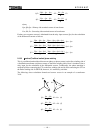
The algorithm of this element is given by the following equation:
ΔId < 0.15×(ΔIp + ΔIn)
where,
ΔId : Change in the differential current Id
(ΔIp + ΔIn) : Change in the restraining current in the positive and negative cycles
Id : Differential current
Ip : Sum of positive input currents
In : Sum of negative input currents
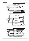
SE operates when the sum of the absolute values of the difference between the instantaneous
values of current data at each current input from one cycle is greater than 0.5 × (CT secondary
rated current).
SE discriminates between healthy and faulty power system conditions and blocks the output of
WDE which may otherwise operate during healthy conditions.
Figure 2.2.2.2 shows CT secondary current waveforms of the incoming and outgoing terminals,