


⎯ 52 ⎯
6 F 2 S 0 8 5 7
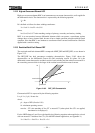
2.10.2 High-set Overcurrent Element HOC
High-set overcurrent element HOC is an instantaneous overcurrent characteristic, and is applied in
the differential circuit. The characteristic is expressed by the following equation:
I
d
≥ kh
Id is defined as follows for three-winding transformer.
I
d
= | kct1⋅I
1
+ kct2⋅I
2
+ kct3⋅I
3
|
where,
kct1, kct2, kct3: CT ratio matching settings of primary, secondary and tertiary winding
HOC is an un-restrained current differential element which can protect a transformer against
damage due to a heavy internal fault, because it has a simple operation principle and high-speed
operation. Note that HOC is not immune to transformer inrush currents and therefore cannot be
applied with a sensitive setting.
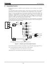
2.10.3 Restricted Earth Fault Element REF
The restricted earth fault element REF is composed of REF_DIF and REF_DEF, as was shown in
Figure 2.3.2.
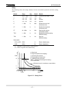
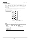
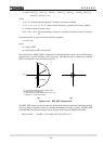
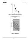
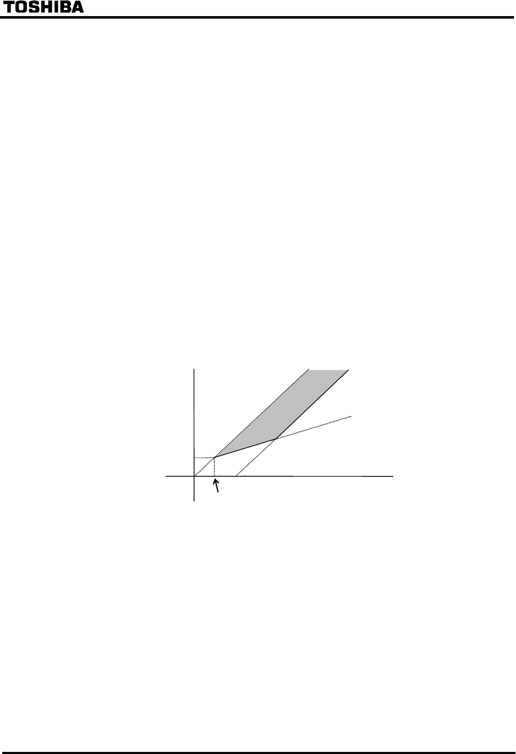
The REF_DIF has dual percentage restraining characteristics. Figure 2.10.2 shows the
characteristics on the differential current (Id) and restraining current (Ir) plane. Id is the
differential current between the residual current of each winding and the neutral current and Ir is
the restraining current which is the larger of the residual current and the neutral current.
I
d
DF2
DF1
max-kct⋅ik
kp
I
r
max-kct
⋅
ik
Figure 2.10.2 REF_DIF Characteristic
Characteristic DF1 is expressed by the following equation:
I
d
≥ p1⋅I
r
+ (1-p1) ⋅ik⋅max-kct
where,
p1 : slope of DF1 (fixed to 10%)
ik : minimum operating current
max-kct : CT ratio matching of line CT to neutral CT (when plural line CTs are applied,
maximum kct is employed.)
For the 1REF element, I
d
and I
r
are calculated by the following equations when applied to a circuit
with one neutral CT and three line CTs. (For the REF element application, see Appendix L.)
I
d
= |1kct1⋅I
1o
+ 1kct2⋅I
2o
+ 1kct3⋅I
3o
+ I
N
|