


3G Storm Series
®
Wheelchairs 92 Part No. 1104849
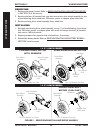
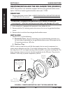
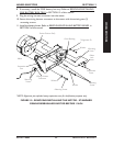
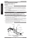
STANDARD GEARLESS/BRUSHLESS MOTOR BEFORE 1/26/04
(FIGURE 10)
Removing.
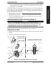
1. Remove the battery boxes. Refer to
REMOVING/INSTALLING BATTERY BOXES in
SECTION 9 of this manual.
2. Unthread the mounting screws that secure the wiring harness connector to the motor.
3. Unplug the wiring harness connector from the motor.
4. If necessary, remove the 22NF battery box tray. Refer to REMOVING/INSTALLING
22NF BATTERY BOX TRAY in SECTION 15 of this manual.
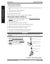
5. Remove the drive wheel from the wheelchair. Refer to REMOVING/INSTALLING
DRIVE WHEELS in this section of the manual.
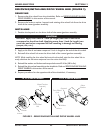
6. Note the mounting position of the motor on the suspension arm before removing the motor.
7. Loosen adjustment screw that secures the motor lock lever in place on the brake release shaft.
NOTE: Alignment pin is located inside of bushing guide on the suspension arm.
8. Remove the mounting screw and washer that secure the alignment pin in place.
9. Slide the alignment pin back out of the end of the motor lock lever.
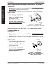
10. Remove the four (4) mounting screws and washers that secure the motor to the
suspension arm.
11. Remove motor with motor lock lever from suspension arm.
12. If replacing motor, remove the motor lock lever from the brake release shaft of the
existing motor.
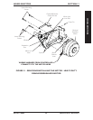
Installing.
NOTE: Do not tighten adjustment screw of motor lock lever until motor is secured in place on
the suspension arm.
1. If necessary, install motor lock lever onto new brake release shaft of motor.
2. Position the new/existing motor with motor lock lever onto the suspension arm in
the mounting position noted from STEP 5 of
REMOVING THE STANDARD
GEARLESS/BRUSHLESS MOTOR in this section of the manual.
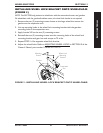
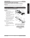
3. Secure motor to the suspension arm with existing four (4) mounting screws.
Torque to 13 ft-lbs.
4. Slide the motor lock lever along brake release shaft until the end is flush with the
bushing guide.
5. Slide alignment pin, located inside of bushing guide, into the end of the motor lock
lever and secure in place with existing mounting screw and washer. Securely tighten.
6. Secure motor lock lever in place on the brake release shaft with existing mounting screw.
7. Install the drive wheel from the wheelchair. Refer to REMOVING/INSTALLING
DRIVE WHEELS in this section of the manual.
SECTION 12 WHEELS/MOTORS
WHEELS/MOTORS