Part No. 1104849 101 3G Storm Series
®
Wheelchairs
ELECTRONICS
SECTION 13ELECTRONICS
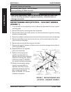
REMOVING/INSTALLING THE MKIV CONTROLLER
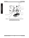
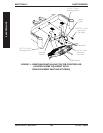
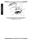
REMOVING MKIV CONTROLLER (WHEELCHAIRS EQUIPPED
WITH NON-POWERED SEATING SYSTEMS) (FIGURE 2)
1. Remove the battery boxes. Refer to REMOVING/INSTALLING THE BATTERY
BOXES in SECTION 9 of this manual.
2. Remove the controller shroud (if applicable).
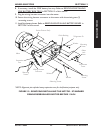
3. Remove the 5/16-18 x 1-inch hex head cap screw that secures the controller
bracket and jumper cable to the base frame.
4. Remove the 5/16-18 x 1-inch hex head cap screw that secures the controller
bracket to the base frame.
5. Remove the 8-32 x 1/2-inch mounting screw and lockwasher that secures the front
of the MKIV controller and jumper cable to the controller bracket.
6. Remove the two (2) 8-32 x 1/2-inch mounting screws that secure the rear of the
MKIV controller to the controller bracket.
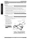
INSTALLING MKIV CONTROLLER (WHEELCHAIRS EQUIPPED
WITH NON-POWERED SEATING SYSTEMS) (FIGURE 2)
1. Secure the rear of the MKIV controller to the controller bracket with two (2) of
the NEW 8-32 x 1/2-inch mounting screws. Securely tighten.
2. Secure the front of the MKIV controller and one end of the jumper cable to the
controller bracket with one (1) of the NEW 8-32 x 1/2-inch mounting screw and
lockwasher. Securely tighten.
3. Secure one side of the controller bracket to the base frame as shown in FIGURE 2
with one (1) of the NEW 5/16-18 x 1-inch hex head cap screw. Securely tighten.
4. Secure the other side of the controller bracket and opposite end of jumper cable to
the base frame as shown in FIGURE 2 with the remaining NEW 5/16-18 x 1-inch hex
head cap screw. Securely tighten.
5. Reinstall the controller shroud (if applicable).
6. Reinstall the battery boxes. Refer to REMOVING/INSTALLING THE BATTERY
BOXES in SECTION 9 of this manual.


