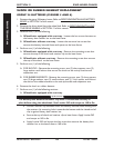
Part No. 1104849 129 3G Storm Series
®
Wheelchairs
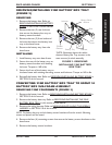
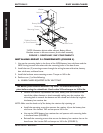
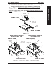
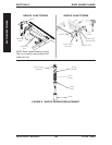
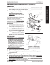
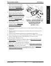
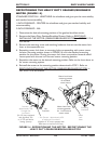
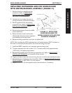
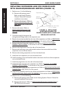
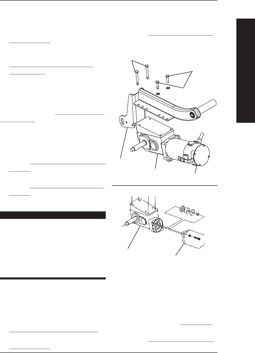
REMOVING/INSTALLING GEARBOX (FIGURE 9)
REMOVING
1. Remove the drive wheels from the wheelchair. Refer to REMOVING/INSTALLING
DRIVE WHEELS in SECTION 12 of this manual.
2. Remove the drive wheel hub from the
existing gearbox drive shaft. Refer to
REMOVING/INSTALLING DRIVE
WHEEL HUBS in SECTION 12 of this
manual.
NOTE: Note mounting position of gearbox to
suspension arm before disassembly.
NOTE: To reposition the gearbox on the
suspension arm, refer to
ADJUSTING WEIGHT
DISTRIBUTION in this section of the manual.
3. Remove the four (4) hex screws and
two (2) washers that secure the existing
motor/gearbox to the suspension arm.
4. Remove existing motor from gearbox.
Refer to REMOVING/INSTALLING THE
MOTOR in SECTION 12 of this manual.
5. Install existing motor onto NEW gearbox.
Refer to REMOVING/INSTALLING THE
MOTOR in SECTION 12 of this manual.
INSTALLING
CAUTION
The REAR hex screws that secure
the gearbox to the suspension arm
MUST be 5/16-18 x 2-1/2-inches long
and the FRONT hex screws that
secure the gearbox to the suspension
arm MUST be 5/16-18 x 1-1/4-inches
long. Otherwise damage to the
gearbox casting can result.
1. Position NEW gearbox with noted mounting holes.
2. When reassembling gearbox to suspension arm, use Loctite 242 and torque hex
screws to 160 in-lbs.
NOTE: Replace any parts that show signs of wear or damage.
3. Reinstall the drive wheel hub to the new gearbox driveshaft. Refer to REMOVING/
INSTALLING DRIVE WHEEL HUBS in SECTION 12 of this manual.
4. Reinstall the drive wheels onto the wheelchair. Refer to REMOVING/INSTALLING
DRIVE WHEELS in SECTION 12 of this manual.
RWD WHEELCHAIRS SECTION 15
RWD WHEELCHAIRS
5/16-18 x
1-1/4-inch
Hex Screws
Gearbox
Suspension
Arm
FIGURE 9 - REMOVING/
INSTALLING GEARBOX
Motor
5/16-18 x 2-1/2-inch
Hex Screws
Gearbox
Motor


