


3G Storm Series
®
Wheelchairs 30 Part No. 1104849
SEAT FRAME
SECTION 6
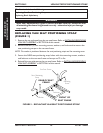
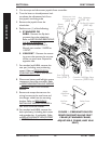
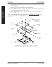
3. Cut tie wraps and disconnect joystick from controller.
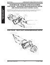
4. Turn the lever on the adjustment lock
to release the adjustment lock from
the joystick mounting tube.
5. Remove the joystick from the
wheelchair.
6. Perform one (1) of the following:
A. STANDARD OR
ASBA - Remove the flip-back
armrests from the wheelchair.
Refer to INSTALLING/REMOVING
FLIP BACK ARMRESTS in
SECTION 4 of the Owner’s
Manual, part number 1104782 or
1123757.
B. VAN SEAT - Remove the mount-
ing screw that secures the armrest
to the van seat frame. Repeat for
opposite side.
7. For standard and ASBA, remove the
seat pan (including seat positioning
straps). Refer to REMOVING/IN-
STALLING SEAT PAN in this section
of the manual.
8. Disconnect battery and left/right motor
connectors from the controller. Refer
to REMOVING/INSTALLING WIRING
HARNESS in SECTION 10 of this
manual.
9. Remove tie-wraps that secures the
wiring harness to the seat frame and
the charger cable from its mounting
bracket. Refer to REMOVING/
INSTALLING WIRING HARNESS in
SECTION 10 of this manual.
10. For standard and ASBA, remove the
back upholstery (including back canes
and spreader bar, if applicable). Refer
to REPLACING BACK UPHOLSTERY
in SECTION 5 of this manual.
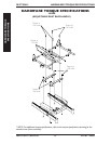
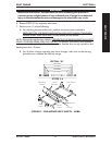
SEAT FRAME
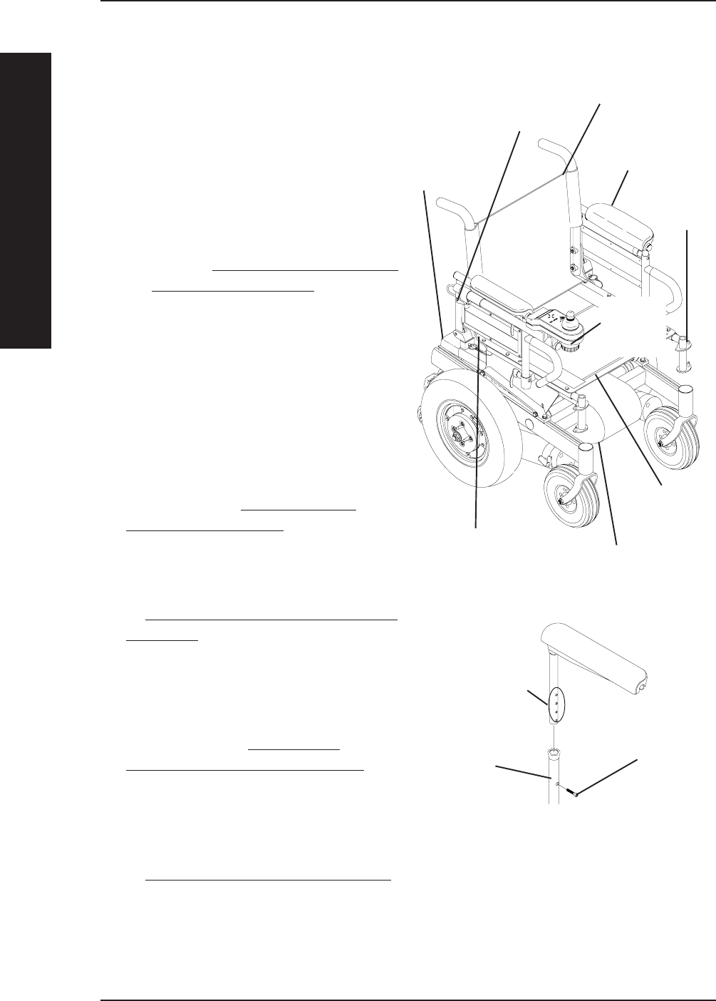
FIGURE 1 - PREPARATION FOR
REMOVING/INSTALLING SEAT
FRAME (STANDARD FRAME,
ADJUSTABLE FRAME, AND VAN
SEAT)
Joystick
(STEPS
3,5)
Footrest
Location
(STEP 1)
Battery
Boxes
(STEP 2)
Adjustment Lock
Lever for Joystick
(STEP 4)
Flip Back Armrests
(STEP 6A)
Seat Pan
(Step 7)
Controller, Left/Right Motor
Connectors (STEPS 8,9)
Back Upholstery
(STEP 10)
Seat Positioning
Strap (STEP 7)
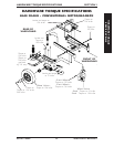
Socket Screw
Van Seat
Base
Height
Adjustment
Holes