


Appendix 1 Outline Drawings
Appendix 1.10 Grounding Plate and Clamp Fitting Outline Drawings
79
Appendix 1.10 Grounding Plate and Clamp Fitting Outline Drawings
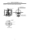
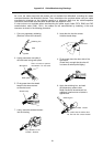
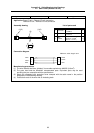
The shield wire generally only needs to be
grounded to the connector's case frame.
However, the effect can be improved by
directly grounding to the grounding plate as
shown on the right.
Install the grounding plate near each unit.
Peel part of the cable sheath as shown on
the right to expose the shield sheath. Press
that section against the grounding plate
with the clamp fitting. Note that if the cable
is thin, several can be clamped together.
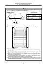
Install the grounding plate directly onto the
cabinet or connect a grounding wire so that
sufficient frame grounding is achieved.
If the AERSBAN-SET, containing the
grounding plate and clamp fitting, is
required, please contact Mitsubishi.
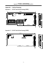
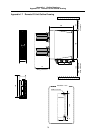
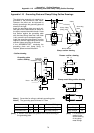
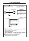
• Outline drawing
11
35
6
22
35
a
c
24
0
-0.2
17.5
6
3
7
b ± 0.3
Grounding plate
outline drawing
2-Ø5 hole
Installation hole
Note 1 M4 screw
Note 1) Screw hole for wiring to cabinet's grounding plate
Note 2) The grounding plate thickness is 1.6mm
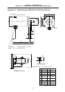
a b c Enclosed fittings L
AERSBAN-DSET 100 86 30 Two clamp fittings A Clamp fitting A 70
AERSBAN-ESET 70 56 – One clamp fitting B Clamp fitting B 45
(Note) a, b and c in the table are symbols in the outline drawing of (Note) L in the table is a
the grounding plate. symbol in the
outline drawing
of the clamp
metal fittings.
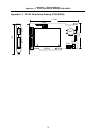
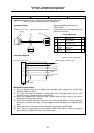
MAX L
10
30
+0.3
0
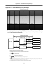
Clamp metal fitting outline drawing
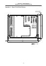
24
Cable
Grounding
plate
Shield sheath
Clamp fitting
(Fitting A,B)
Clamp section drawing
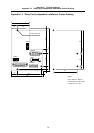
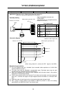
Presser
40
Presser outline drawing
29
3
3
+0.3
0
20
0
-0.2
24
7
12