7. Remote I/O Unit Connection
7.14 Setting of Channel No. when Using Multiple Remote I/O Units
68
7.14 Setting of Channel No. when Using Multiple Remote I/O Units
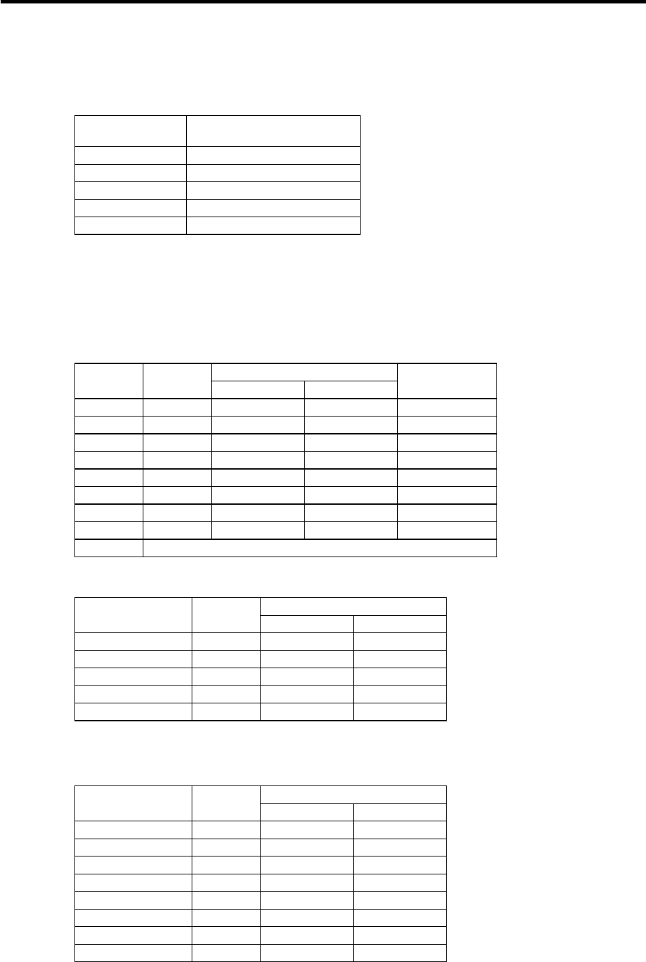
When the remote I/O unit is connected with serial links (MC link B), multiple units can be used as long
as the total No. of occupied channels is within 8 channels.
Unit name
No. of occupied serial
link channels
FCUA-DX10* 1
FCUA-DX11* 2
FCUA-DX12* 2
FCUA-DX13* 2
FCUA-DX14* 2
When using multiple remote I/O units, a characteristic station No. must be set for each unit. The
FCUA-DX10* unit has one station No. setting switch, and FCUA-DX11*, DX12*, DX13* and DX14*
units have two switches. Each of these switches must be set to a characteristic station No.
The device address in each unit is determined according to the station No. Use the station No. setting
switch to set the device address.
Relation between rotary switches and device assignments
Device assignment
Setting
value
Station
No.
DI DO
No. of I/O
points (max)
0 0 X00~X1F Y00~Y1F 32 points
1 1 X20~X3F Y20~Y3F 32 points
2 2 X40~X5F Y40~Y5F 32 points
3 3 X60~X7F Y60~Y7F 32 points
4 4 X80~X9F Y80~Y9F 32 points
5 5 XA0~XBF YA0~YBF 32 points
6 6 XC0~XDF YC0~YDF 32 points
7 7 XE0~XFF YE0~YFF 32 points
8~F Cannot be used
<Device assignment example 1>
Device assignment
Rotary switch
setting value
Station
No.
DI DO
0 0 X00~X1F Y00~Y1F
1 1 X20~X3F Y20~Y3F
2 2 X40~X5F Y40~Y5F
3 3 X60~X7F Y60~Y7F
4 4 X80~X9F Y80~Y9F
(Note) Refer to the next page for a configuration example.
<Device assignment example 2>
Device assignment
Rotary switch
setting value
Station
No.
DI DO
0 0 X00~X1F Y00~Y1F
1 1 X20~X3F Y20~Y3F
2 2 X40~X5F Y40~Y5F
3 3 X60~X7F Y60~Y7F
4 4 X80~X9F Y80~Y9F
5 5 XA0~XBF YA0~YBF
6 6 XC0~XDF YC0~YDF
7 7 XE0~XFF YE0~YFF
(Note) Refer to the next page for a configuration example.


