


5. Base I/O Unit Connection
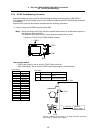
5.2 Base I/O Connection System Drawing
32
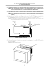
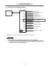
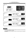
5.2 Base I/O Connection System Drawing
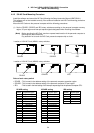
CF10
SV1
SV2
ENC1
SKIP
RIO1
RIO2
CF31
CF32
CF33
CF34
CR31
DCIN
>
0
1
CF10
SW1 SW 2
Servo drive unit
(spindle and NC servo axis)
Servo drive unit
(auxiliary axes)
Encoder 1ch
(1st spindle encoder)
Sensor signal (skip)
Remote I/O unit, part system 1
DI (machine input)
DI (machine input)
DO (machine output)
DO (machine output)
Add-on PCB
NC card
F010 cable
SH21 cable
Base I/O unit
SH21 cable
F040 cable
SH41 (FCUA-R211) cable
SH41 (FCUA-R211) cable
R301 cable
R301 cable
R301 cable
R301 cable
Enclosed cable
F070 (FCUA-R220) cable
External power (24VDC)
Remote I/O unit, part system 2
(future expansion)
>
(Note) Refer to "7. Remote I/O Unit Connection" for add-on PCB connections.
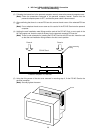
Turn the NC Card's power ON before turning the base I/O unit's power ON.
If the base I/O unit's power is turned ON first, the current will be led to the NC Card from
the connection cable. This will prevent the personal computer or the cards in the
personal computer from starting up properly.
CAUTION