


Appendix 2 Cable Manufacturing Drawings
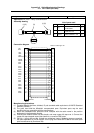
2.19 ENC-SP1 Cable (Spindle drive unit)
100
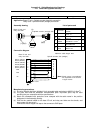
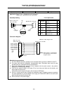
Cable type name: ENC-SP1 cable Appendix 2.19
Application: Base I/O unit – Spindle drive unit connection
Relay card – Spindle drive unit connection
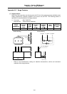
Assembly drawing
(1)(2)(3)
(4)
(5)(6)
ENC-SP1
ENC-SP1
Base I/O unit and
relay card side
Spindle drive unit side
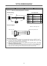
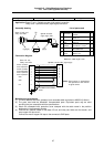
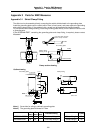
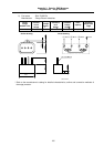
Connection diagram
ENC1A (ENC2A)
ENC1A*(ENC2A*)
ENC1B (ENC2B)
ENC1B*(ENC2B*)
ENC1Z (ENC2Z)
ENC1Z*(ENC2Z*)
GND
GND
+5V
1
6
2
7
3
8
4
5
9
2
12
3
13
4
14
1
5
FG
Base I/O unit,
Relay card side
Spindle drive unit side
Maximum cable length: 50m
Case frame
(Note) Signal names in parentheses
are equivalent to the channel
2 signal names.
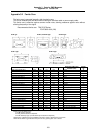
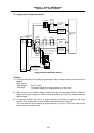
Manufacturing precautions
(1) The wire material shall be a shielded, 6-pair stranded cable equivalent to AWG24 (0.2mm
2
).
(2) The parts used shall be Mitsubishi recommended parts. Equivalent parts may be used
providing they are compatible with the specifications.
(3) Attach the nameplate with protective cover stamped with the cable name in the position
designated in the assembly drawing.
(4) Fold the wire material shield on the base I/O unit and relay card side over the sheath, and
wrap copper foil tape over it.
Connect the wound cooper foil tape to the connector's GND plate.
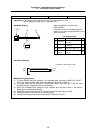
(5) Part No. 5 (plug) and part No. 6 (shell) are solderless types. If soldering types are required,
use parts equivalent to 10120-3000VE for the plug and 10320-52FO-008 for the shell (both
parts manufactured by Sumitomo 3M).
(6) Do not connect a +5V power supply.
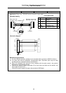
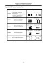
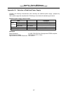
List of parts used
No. Part name Recommended part type Qty
1 Connector
Hirose Electric
CDE-9PF
1
2 Contact
Hirose Electric
CD-PC-111
8
3
Connector
case
Hirose Electric
HDE-CTH
1
4
Wire
material
Bando Electric Wire
DPVVSB 6P × 0.2 mm
2
(1)
5 Plug
Sumitomo 3M
10120-6000EL
1
6 Shell
Sumitomo 3M
10320-3210-000
1