


5. Base I/O Unit Connection
5.5 Base I/O Unit Input/Output Specifications
43
5.5.10 Connection of Sensor Signal (skip)
Connect the sensor signal (skip) to SKIP on the base I/O unit. The sensor signal is used for processing
the high-speed signals. Always shield the cable.
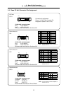
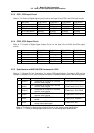
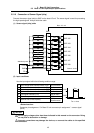
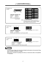
(1) Sensor signal (skip) cable
Base I/O unit
Stabilized power
2.2kΩ
2.2kΩ
2.2kΩ
2.2kΩ
2.2kΩ
2.2kΩ
2.2kΩ
2.2kΩ
2
10
3
11
5
13
6
14
1,8,9,15
+24V
GND
FG
FG
SKIP IN1
SKIP IN2
SKIP IN3
SKIP IN4
SKIP IN5
SKIP IN6
SKIP IN7
SKIP IN8
Control circuit
SKIP
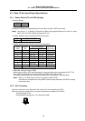
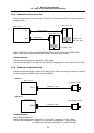
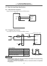
(2) Input conditions
Use the input signal within the following condition range.
1 Input voltage when external contact is ON 25.2V or more
2 Input current when external contact is ON 9mA or more
3 Input voltage when external contact is OFF 4V or less
4 Input current when external contact is OFF 1mA or less
5 Input signal hold time (Ton) 2ms or more
6 Internal response time 0.08ms or less
7 Machine side contact capacity
+30V or more,
16mA or more
<Related section>
Connector pin assignment: “5.4 Base I/O unit connector pin assignment” – sensor signal
(SKIP)
Do not apply voltages other than those indicated in this manual on the connector. Doing
so may lead to destruction or damage.
Incorrect connections may damage the devices, so connect the cables to the specified
connectors.
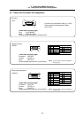
Ton
+24V
GND
t
>
_
Ton 2ms
CAUTION