


6. Relay Card (HR682) Connection
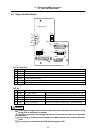
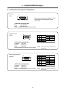
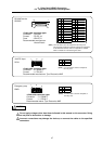
6.5 Relay Card Input/Output Specifications
49
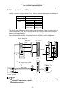
6.5.3 Connection of Spindle Encoder
Refer to "5.5.9 Connection of Spindle Encoder" for details.
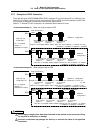
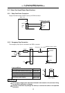
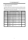
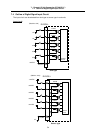
6.5.4 Manual Pulse Generator Connection
Connect the manual pulse generator to the relay card HANDLE connector. The manual pulse generator
can be connected to a max. of three channels.
HANDLE
Relay card
F020/F021/F022 cable
(Channel 1)
F021/F022 cable
F022 cable
(Channel 2)
(Channel 3)
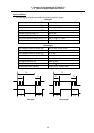
Manual pulse generator connection cables
Channel
Cable name
1 2 3
F020 cable
F021 cable
F022 cable
: Connection possible
<Related sections>
Outline drawing: "Appendix 1.8 Manual Pulse Generator (HD60) Outline Drawing"
Cable manufacturing drawing: "Appendix 2.12 F020 Cable", "Appendix 2.13 F021 Cable" and
"Appendix 2.14 F022 Cable"
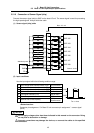
Connector pin assignment: "6.4 Relay Card Connector Pin Assignment"
- Manual Pulse Generator (HANDLE)
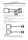
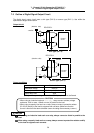
6.5.5 RS-232C Device Connection
Connect the RS-232C device to the RS-232C connector on the relay card using an F390 cable.
The pin assignment for the RS-232C connector differs from a commercially-available RS-232C cable.
Refer to the following related sections for details on manufacturing the cable.
Note that only the DC code (X ON/OFF) method handshake is possible.
<Related sections>
Cable manufacturing drawing: "Appendix 2.18 F390 Cable"
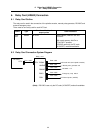
Connector pin assignment: "6.4 Relay Card Connector Pin Assignment"
- RS-232C Device (RS232C)
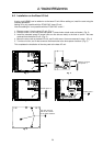
Do not apply voltages other than those indicated in this manual on the connector. Doing
so may lead to destruction or damage.
Incorrect connections may damage the devices, so connect the cables to the specified
connectors.
CAUTION