


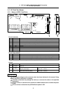

4. NC Card (HR621/HR623/FCU6-HR655) Connection
4.2 NC Card Part Names
17
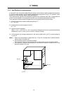
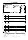
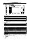
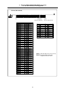
4.2.2 Names of HR623 Card Parts
CF61CF10
BAT
NCLD1
CIO
DPADRIOPADRIRQ
ISABUS ISABUS
ISP
TEST
CF61CF10
WDER
SEMG
5VSALM
3VSALM
3VALM
(3)
(15)
(10)
(11)
(12)
(2)
(1)
(14)
(5)
(13)
(6)
(4)
(7)
(16)(17)(18)
List of connectors
No. Name Function details
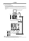
(1) CF61 This is used in the connection with the relay card (HR682). An F011 cable is connected.
(2) CF10 This is used in the connection with the base I/O unit (DX2**, 3**, 4**). An F010 cable is connected.
(3) ISABUS This is connected to the personal computer expansion slot (ISA bus).
(4) BAT This is a battery holder. A Toshiba battery CR2450 is installed.
(5) CIO This is a connector for expansion.
(6) ISP Not used.
(7) TEST Not used.
List of rotary switches
No. Name Function details
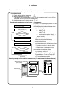
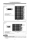
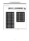
(10) DPADR This is used in the address assignment setting of the personal computer expansion region.
(11) IOPADR This is used in the address assignment setting of the personal computer I/O port region.
(12) IRQ This is used in the level setting of the interrupt request signal to the personal computer CPU.
(Note) Refer to "4.4 ISA NC Card Mounting" for details on setting rotary switches.
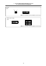
LED list
No. Name Function details
(13) NCLD1
This is the 7-segment LED for the NC status display. This LED changes when at startup, during
alarms, etc.
(14) SEMG
This is the chip LED for the NC system
emergency stop display.
When lit (red) : System in emergency stop.
When not lit : Normal
(15) WDER
This is the chip LED for the remote
communication watchdog display.
When lit (red) : Watchdog alarm.
When not lit : Normal
(16) 5VSALM
This is the chip LED for the circuit power
5VDC low alarm display.
When lit (red) : 5VDC low
When not lit : Normal
(17) 3VSALM
This is the chip LED for the circuit power
3VDC low alarm display.
When lit (red) : 3VDC low
When not lit : Normal
(18) 3VALM
This is the chip LED for the circuit power
3VDC low alarm display.
When lit (red) : 3VDC low
When not lit : Normal
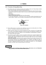
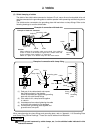
Do not apply voltages on the connector other than those indicated in this manual. Doing
so may lead to destruction or damage.
Incorrect connections may damage the devices, so connect the cables to the specified
connectors.
Do not connect or disconnect the connection cables between each unit while the power
is ON.
Do not connect or disconnect any PCB while the power is ON.
CAUTION