


x
CONTENTS
1. Outline.................................................................................................................................. 1
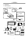
2. Configuration ...................................................................................................................... 2
2.1 System Configuration..................................................................................................... 2
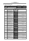
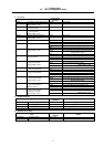
2.2 List of Configuration Units .............................................................................................. 3
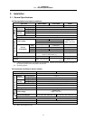
3. Installation........................................................................................................................... 5
3.1 General Specifications ................................................................................................... 5
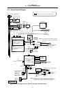
3.2 General System Diagram............................................................................................... 6
3.3 Installation...................................................................................................................... 8
3.3.1 Installation Direction and Spacing........................................................................... 8
3.3.2 Prevention of Foreign Matter Entry......................................................................... 9
3.3.3 Heat Radiation Countermeasures .......................................................................... 10
3.3.4 Noise Countermeasures......................................................................................... 12
4. NC Card Connection........................................................................................................... 15
4.1 NC Card Connection System Diagram........................................................................... 15
4.2 NC Card Part Names ..................................................................................................... 16
4.2.1 Names of HR621 Card Parts.................................................................................. 16
4.2.2 Names of HR623 Card Parts.................................................................................. 17
4.2.3 Names of FCU6-HR655 Unit Parts......................................................................... 18
4.3 Control Unit Connector Pin Assignment ......................................................................... 19
4.4 ISA NC Card Mounting................................................................................................... 23
4.4.1 Before Mounting the ISA NC Card.......................................................................... 23
4.4.2 ISA NC Card Mounting Procedure.......................................................................... 24
4.5 PCI NC Card Mounting................................................................................................... 27
4.5.1 Before Mounting the PCI NC Card ......................................................................... 27
4.5.2 PCI NC Card Mounting Procedure ......................................................................... 28
5. Base I/O Unit Connection................................................................................................... 31
5.1 Base I/O Unit Outline ..................................................................................................... 31
5.2 Base I/O Connection System Drawing ........................................................................... 32
5.3 Base I/O Unit Part Names.............................................................................................. 33
5.4 Base I/O Unit Connector Pin Assignment....................................................................... 35
5.5 Base I/O Unit Input/Output Specifications ...................................................................... 38
5.5.1 Rotary Switch Settings ........................................................................................... 38
5.5.2 RIO1 Terminator..................................................................................................... 38
5.5.3 CF31, CF32 Input Circuit........................................................................................ 39
5.5.4 CF33, CF34 Output Circuit..................................................................................... 39
5.5.5 Specifications of ADD ON PCB Connected to CR31.............................................. 39
5.5.6 Connection of Base I/O Unit Power Supply............................................................ 40
5.5.7 Examples of DI/DO Connection.............................................................................. 41
5.5.8 Connection of Servo Drive Unit .............................................................................. 42
5.5.9 Connection of Spindle Encoder .............................................................................. 42
5.5.10 Connection of Sensor Signal................................................................................ 43
6. Relay Card Connection....................................................................................................... 44
6.1 Relay Card Outline......................................................................................................... 44
6.2 Relay Card Connection System Diagram....................................................................... 44
6.3 Relay Card Part Names ................................................................................................. 45
6.4 Relay Card Connector Pin Assignment .......................................................................... 46
6.5 Relay Card Input/Output Specifications.......................................................................... 48
6.5.1 Relay Card Power Connection ............................................................................... 48
6.5.2 Emergency Stop Connection.................................................................................. 48
6.5.3 Connection of Spindle Encoder .............................................................................. 49
6.5.4 Manual Pulse Generator Connection ..................................................................... 49
6.5.5 RS-232C Device Connection.................................................................................. 49
6.6 Installation on the Base I/O Unit..................................................................................... 50