


3. Installation
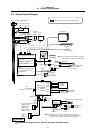
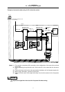
3.3 Installation
14
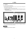
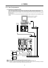
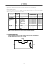
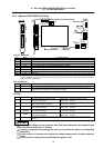
Cables which require shield clamp with a connector cases are shown following table.
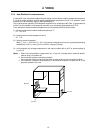
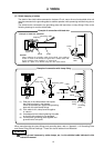
<Shield clamp method>
Fold the wire material shield over the sheath, and wrap copper foil tape over it. Connect the wrapped
copper foil tape to the connector case GND plate.
Treatment of cable ends
Unit name
Connector
name
Connection destination
Connection origin
Connection
destination
NC Card
(HR621/HR623/
FCU6-HR655)
CF10
CF61
Base I/O unit
Relay card
(NC Card) Not required
(NC Card) Not required
Not required
Not required
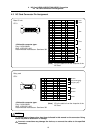
Base I/O unit
(FCU6-DX2
∗∗, 3∗∗,
4
∗∗)
CF10
SV1
SV2
ENC1
SKIP
PI01
PI02
NC Card
Servo drive unit
Servo drive unit
Spindle encoder
Skip
Remote I/O unit
Remote I/O unit
(Base I/O unit) Not required
(Base I/O unit) Required
(Base I/O unit) Required
(Base I/O unit) Required
(Base I/O unit) Required
(Base I/O unit) Required
(Base I/O unit) Required
Not required
Not required
Not required
Not required
Not required
Not required
Not required
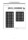
Relay card
(HR682)
CF61
ENC#2
HANDLE
RS232C
NC Card
Spindle encoder
Manual pulse generator
RS-232C (I/O device)
(Note)
(Relay card) Not required
(Relay card) Required
(Relay card) Required
(Relay card) Required
Not required
Not required
Not required
Not required
(Note) RS-232C uses only the DC code (X ON/OFF) method handshake.
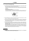
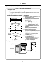
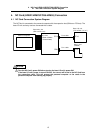
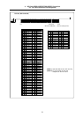
(3) Connecting Spark Killers
Connect a spark killer on the coil or relay contact in parallel for noise countermeasures.
Use spark killers which are 0.033~0.1µF, 10~120Ω.
Coil
Contact
E
SK
SK