


3. Installation
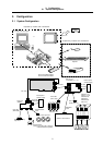
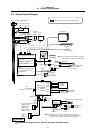
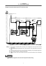
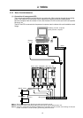
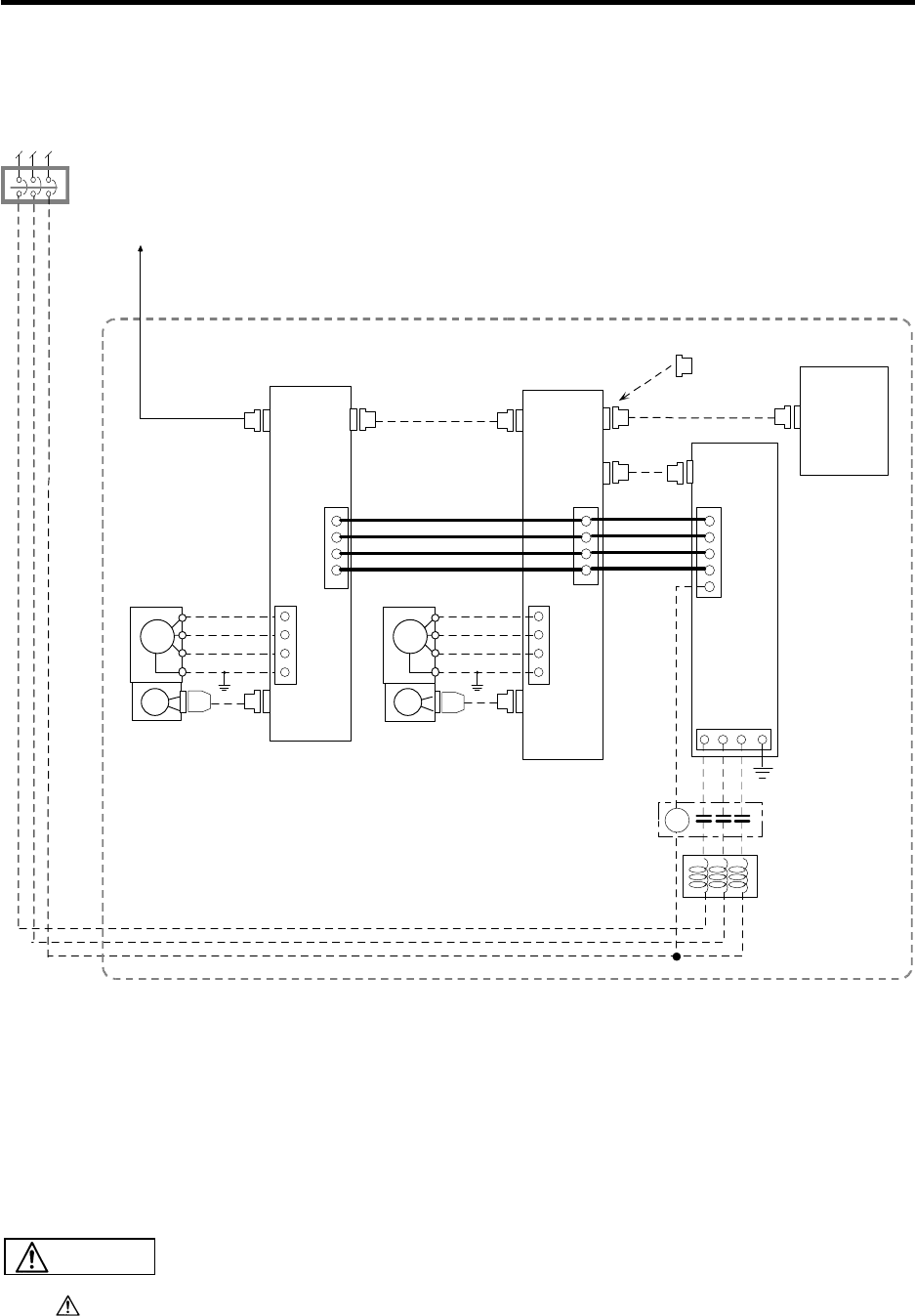
3.2 General System Diagram
7
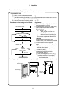
Example of connection when using V1/V2 in the drive section
CN1A
CN1B
CN2
SM
PG
U
V
W
E
SM
PG
CN1A
CN1B
CN2
RSTE
CN4
P
N
R0
S0
MC1
P
N
R0
S0
B-AL
MC
CN4
U
V
W
E
RST
Connection to base I/O unit
SV1 and SV2
Note (1)
SH21 cable
Servo drive unit
MDS-B/C1 Series
Note (2)
SH21 cable
Servo drive unit
MDS-B/C1 Series
Terminator
A-TM
Battery
unit
MDS-A-BT-4(4 axes)
MDS-A-BT-2(2 axes)
Power
supply unit
AC servomotor
AC servomotor
Motor end detector
Motor end detector
SH21 cable
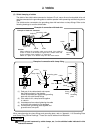
(Note) (1) Drive section connections differ according to the configuration of the servo drive unit and
motor used.
(2) When connecting the spindle drive unit, set the axis No. to the value after the last servo
axis.
(3) Connect the last axis (the axis to be connected to the battery unit) to the power supply unit.
(4) When using a terminator, connect to the last axis.
(5) Always wire the control unit's signal wire away from the drive section's drive lines/power
lines.
Separate the signal wire from the drive line/power line when wiring.
CAUTION