8XC251SA, SB, SP, SQ USER’S MANUAL
Index-4
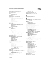
detection, 6-3
edge-triggered, 6-4
enable/disable, 6-5
exiting idle mode, 12-5
exiting powerdown mode, 12-6
external, 6-3, 6-11
global enable, 6-5
instruction completion time, 6-10
latency, 6-9–6-13
level-triggered, 6-4
PCA, 6-5
polling, 6-9, 6-10
priority, 6-1, 6-3, 6-4, 6-7
priority within level, 6-7
processing, 6-9–6-15
request, See Interrupt request
response time, 6-9, 6-10
sampling, 6-3, 6-10
serial port, 6-5
service routine (ISR), 6-4, 6-9, 6-14, 6-15
sources, 6-3
timer/counters, 6-4
vector cycle, 6-14
vectors, 3-3, 6-4
INTR bit
and RETI instruction, 4-16, 5-16
IPH0, 3-17, 3-18, 6-3, 6-8, 6-14, C-2, C-3, C-15
bit definitions, 6-7
IPL0, 3-17, 3-18, 6-3, 6-8, 6-14, C-2, C-3, C-16
bit definitions, 6-7
ISR, See Interrupts, service routine
J
JB instruction, 5-14, A-24
JBC instruction, 5-14, A-24
JC instruction, A-24
JE instruction, A-24
JG instruction, A-24
JLE instruction, A-24
JMP instruction, A-24
JNB instruction, 5-14, A-24
JNC instruction, A-24
JNE instruction, A-24
JNZ instruction, A-24
JSG instruction, A-25
JSGE instruction, A-25
JSL instruction, A-24
JSLE instruction, A-25
Jump instructions
bit-conditional, 5-14
compare-conditional, 5-14
unconditional, 5-15
JZ instruction, A-24
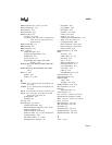
K
Key bytes, See Encryption array
L
Latency, 6-9
LCALL instruction, 5-15, A-24
LJMP instruction, 5-15, A-24
Lock bits
programming and verifying, 14-1, 14-7
protection types, 14-8
setup for programming and verifying, 14-4–
14-5
Logical instructions, 5-9
table of, A-17
M
MCS 251 microcontroller, 2-1
core, 2-4
features, 2-1
MCS 51 microcontroller, 2-1
Memory space, 2-4, 3-1, 3-5–3-10
compatibility, See Compatibility (MCS 251
and MCS 51 architectures)
regions, 3-2, 3-5
reserved locations, 3-5
Miller effect, 11-5
MOV instruction, A-19, A-20, A-21
for bits, 5-11, A-23
MOVC instruction, 3-2, 5-10, A-21
Move instructions
table of, A-19
MOVH instruction, 5-10, A-21
MOVS instruction, 5-10, A-21
MOVX instruction, 3-2, 5-10, A-21
MOVZ instruction, 5-10, A-21
MUL instruction, 5-9
Multiplication, 5-9


