


8XC251SA, SB, SP, SQ USER’S MANUAL
C-8
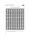
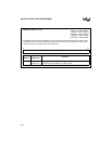
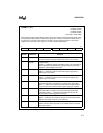
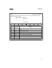
CCAPxH, CCAPxL (x = 0–4)
Address: CCAP0H,L S:FAH, S:EAH
CCAP1H,L S:FBH, S:EBH
CCAP2H,L S:FCH, S:ECH
CCAP3H,L S:FDH, S:EDH
CCAP4H,L S:FEH, S:EEH
Reset State: XXXX XXXXB
PCA Module Compare/Capture Registers. These five register pairs store the 16-bit comparison value
or captured value for the corresponding compare/capture modules. In the PWM mode, the low-byte
register controls the duty cycle of the output waveform.
7 0
High/Low Byte of Compare/Capture Values
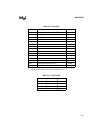
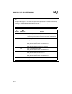
Bit
Number
Bit
Mnemonic
Function
7:0 CCAP
x
H.7:0
CCAP
x
L.7:0
High byte of PCA comparison or capture values.
Low byte of PCA comparison or capture values.