


8XC251SA, SB, SP, SQ USER’S MANUAL
A-120
Flags:
Example: The label "RELADR" is assigned to an instruction at program memory location 0123H. The
instruction
SJMP RELADR
assembles into location 0100H. After executing the instruction, the PC contains 0123H.
(Note: In the above example, the instruction following SJMP is located at 102H. Therefore,
the displacement byte of the instruction is the relative offset (0123H–0102H) = 21H. Put
another way, an SJMP with a displacement of 0FEH would be a one-instruction infinite loop.)
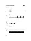
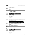
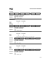
Binary Mode Source Mode
Bytes: 22
States: 44
Hex Code in: Binary Mode = [Encoding]
Source Mode = [Encoding]
Operation: SJMP
(PC) ← (PC) + 2
(PC) ← (PC) + rel
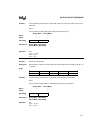
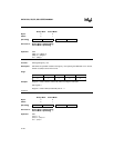
SLL <src>
Function: Shift logical left by 1 bit
Description: Shifts the specified variable to the left by 1 bit, replacing the LSB with zero. The bit shifted
out (MSB) is stored in the CY bit.
Flags:
Example: Register 1 contains 0C5H (11000101B). After executing the instruction
SLL register 1
Register 1 contains 8AH (10001010B) and CY = 1.
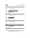
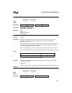
Variations
SLL Rm
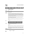
Binary Mode Source Mode
Bytes: 32
States: 21
CY AC OV N Z
—————
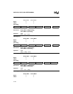
[Encoding] 1 0 0 0 0 0 0 0 rel. addr
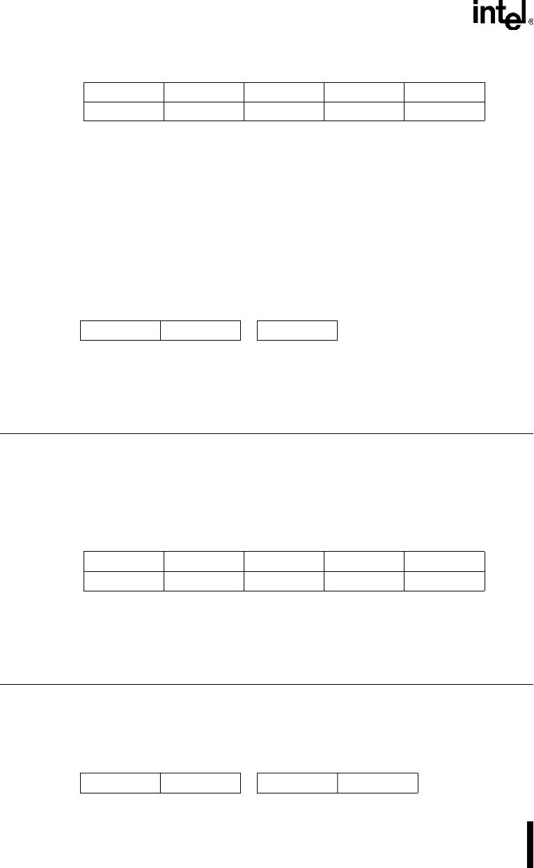
CY AC OV N Z
✓ ——✓✓
[Encoding] 0 0 1 1 1 1 1 0 s s s s 0 0 0 0