6-3
INTERRUPT SYSTEM
6.2 8XC251SA, SB, SP, SQ INTERRUPT SOURCES
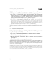
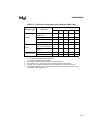
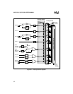
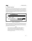
Figure 6-1 illustrates the interrupt control system. The 8XC251Sx has eight interrupt sources;
seven maskable sources and the TRAP instruction (always enabled). The maskable sources in-
clude two external interrupts (INT0# and INT1#), three timer interrupts (timers 0, 1, and 2), one
programmable counter array (PCA) interrupt, and one serial port interrupt. Each interrupt (except
TRAP) has an interrupt request flag, which can be set by software as well as by hardware (see
Table 6-3, “Interrupt Control Matrix”). For some interrupts, hardware clears the request flag
when it grants an interrupt. Software can clear any request flag to cancel an impending interrupt.
6.2.1 External Interrupts
External interrupts INT0# and INT1# (INTx#) pins may each be programmed to be level-trig-
gered or edge-triggered, dependent upon bits IT0 and IT1 in the TCON register (see Figure 8-6
on page 8-8). If ITx = 0, INTx# is triggered by a detected low at the pin. If ITx = 1, INTx# is neg-
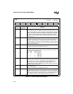
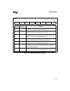
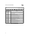
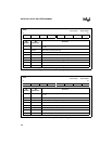
ative-edge triggered. External interrupts are enabled with bits EX0 and EX1 (EXx) in the IE0 reg-
ister (see Figure 6-2, “Interrupt Enable Register”). Events on the external interrupt pins set the
interrupt request flags IEx in TCON. These request bits are cleared by hardware vectors to service
routines only if the interrupt is negative-edge triggered. If the interrupt is level-triggered, the in-
terrupt service routine must clear the request bit. External hardware must deassert INTx# before
the service routine completes, or an additional interrupt is requested. External interrupt pins must
be deasserted for at least four state times prior to a request.
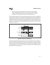
External interrupt pins are sampled once every four state times (a frame length of 666.4 ns at 12
MHz). A level-triggered interrupt pin held low or high for any five-state time period guarantees
detection. Edge-triggered external interrupts must hold the request pin low for at least five state
times. This ensures edge recognition and sets interrupt request bit EXx. The CPU clears EXx au-
tomatically during service routine fetch cycles for edge-triggered interrupts.
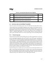
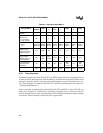
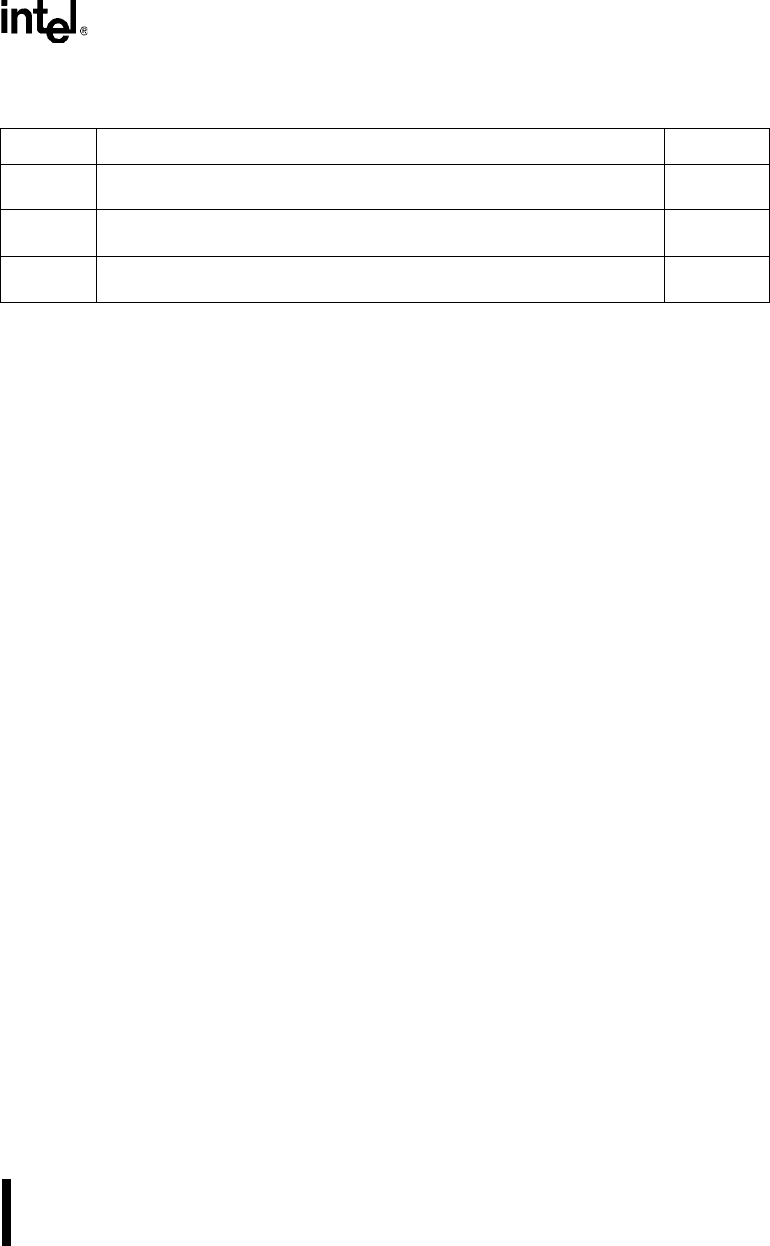
Table 6-2. Interrupt System Special Function Registers
Mnemonic Description Address
IE0 Interrupt Enable Register. Used to enable and disable programmable
interrupts. The reset value of this register is zero (interrupts disabled).
S:A8H
IPL0 Interrupt Priority Low Register. Establishes relative four-level priority for
programmable interrupts. Used in conjunction with IPH0.
S:B8H
IPH0 Interrupt Priority High Register. Establishes relative four-level priority for
programmable interrupts. Used in conjunction with IPL0.
S:B7H
NOTE: Other special function registers are described in their respective chapters.


