


8XC251SA, SB, SP, SQ USER’S MANUAL
11-4
For a more in-depth discussion of crystal specifications, ceramic resonators, and the selection of
C1 and C2 see Applications Note AP-155, “Oscillators for Microcontrollers,” in the Embedded
Applications handbook.
11.3.2 On-chip Oscillator (Ceramic Resonator)
In cost-sensitive applications, you may choose a ceramic resonator instead of a crystal. Ceramic
resonator applications may require slightly different capacitor values and circuit configuration.
Consult the manufacturer’s data sheet for specific information.
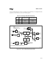
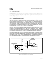
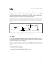
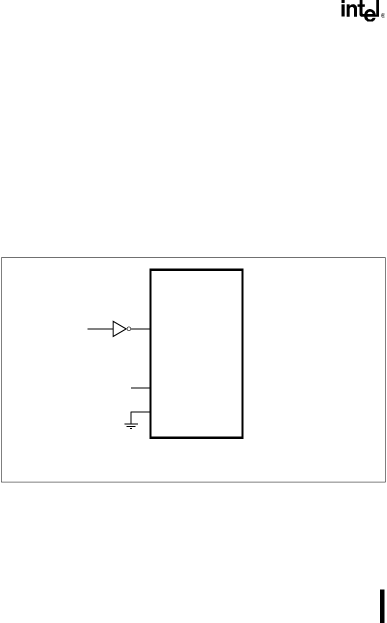
11.3.3 External Clock
To operate the CHMOS 8XC251Sx from an external clock, connect the clock source to the
XTAL1 pin as shown in Figure 11-3. Leave the XTAL2 pin floating. The external clock driver
can be a CMOS gate. If the clock driver is a TTL device, its output must be connected to V
CC
through a 4.7 kΩ pullup resistor.
Figure 11-3. External Clock Connection
XTAL2
V
SS
XTAL1
N/C
External
Clock
CMOS
Clock Driver
A4142-03
Note: If TTL clock driver is used, connect a 4.7kΩ pullup resistor from driver output to V
CC.