8XC251SA, SB, SP, SQ USER’S MANUAL
A-32
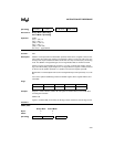
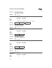
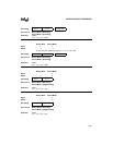
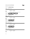
ADD Rm,@DRk
Binary Mode Source Mode
Bytes: 43
States: 43
[Encoding]
Hex Code in: Binary Mode = [A5][Encoding]
Source Mode = [Encoding]
Operation: ADD
(Rm) ← (Rm) + ((DRk))
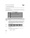
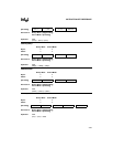
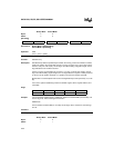
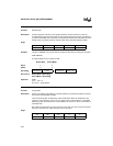
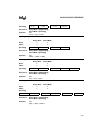
ADDC A,<src>
Function: Add with carry
Description: Simultaneously adds the specified byte variable, the CY flag, and the accumulator contents,
leaving the result in the accumulator. If there is a carry out of bit 7 (CY), the CY flag is set; if
there is a carry out of bit 3 (AC), the AC flag is set. When adding unsigned integers, the CY
flag indicates that an overflow occurred.
If there is a carry out of bit 6 but not out of bit 7, or a carry out of bit 7 but not bit 6, the OV
flag is set. When adding signed integers, the OV flag indicates a negative number produced
as the sum of two positive operands, or a positive sum from two negative operands.
Bit 6 and bit 7 in this description refer to the most significant byte of the operand (8, 16, or 32
bit)
Four source operand addressing modes are allowed: register, direct, register-indirect, and
immediate.
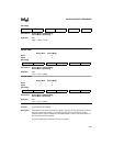
Flags:
Example: The accumulator contains 0C3H (11000011B), register 0 contains 0AAH (10101010B), and
the CY flag is set. After executing the instruction
ADDC A,R0
the accumulator contains 6EH (01101110B), the AC flag is clear, and the CY and OV flags
are set.
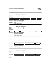
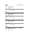
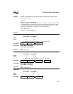
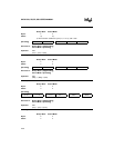
Variations
ADDC A,#data
Binary Mode Source Mode
Bytes: 22
States: 11
0 0 1 0 1 1 1 0 u u u u 1 0 1 1 s s s s 0 0 0 0
CY AC OV N Z
✓✓✓✓✓


