


11-7
MINIMUM HARDWARE SETUP
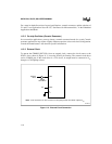
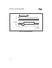
While the RST pin is high ALE, PSEN#, and the port pins are weakly pulled high. The first ALE
occurs 32T
OSC
after the reset signal goes low. For this reason, other devices can not be synchro-
nized to the internal timings of the 8XC251Sx.
NOTE
Externally driving the ALE and/or PSEN# pins to 0 during the reset routine
may cause the device to go into an indeterminate state.
Powering up the 8XC251Sx without a reset may improperly initialize the
program counter and SFRs and cause the CPU to execute instructions from an
undetermined memory location.
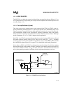
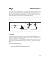
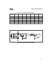
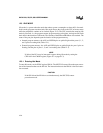
11.4.4 Power-on Reset
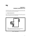
To automatically generate a reset at power-on, connect the RST pin to the V
CC
pin through a 1-µF
capacitor as shown in Figure 11-1.
When V
CC
is applied, the RST pin rises to V
CC
, then decays exponentially as the capacitor charg-
es. The time constant must be such that RST remains high (above the turn-off threshold of the
Schmitt trigger) long enough for the oscillator to start and stabilize, plus 64T
OSC
. At power-on,
V
CC
should rise within approximately 10 ms. Oscillator start-up time is a function the crystal fre-
quency; typical start-up times are 1 ms for a 10 MHz crystal and 10 ms for a 1 Mhz crystal.
During power-on, the port pins are in a random state until forced to their reset state by the asyn-
chronous logic.
Reducing V
CC
quickly to 0 causes the RST pin voltage to momentarily fall below 0 V. This volt-
age is internally limited and does not harm the device.