


8-5
TIMER/COUNTERS AND WATCHDOG TIMER
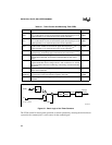
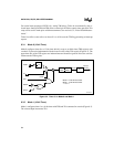
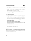
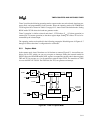
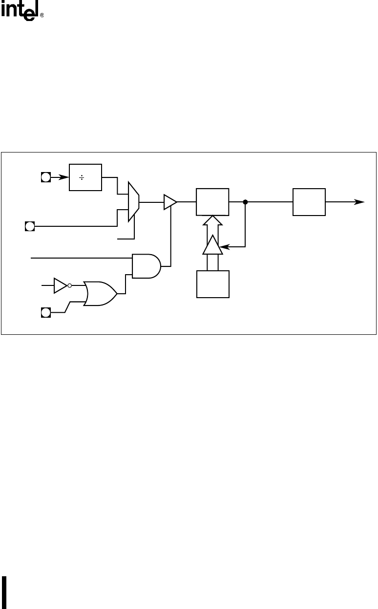
8.3.3 Mode 2 (8-bit Timer With Auto-reload)
Mode 2 configures timer 0 as an 8-bit timer (TL0 register) that automatically reloads from the
TH0 register (Figure 8-3). TL0 overflow sets the timer overflow flag (TF0) in the TCON register
and reloads TL0 with the contents of TH0, which is preset by software. When the interrupt re-
quest is serviced, hardware clears TF0. The reload leaves TH0 unchanged. See section 8.5.1,
“Auto-load Setup Example.”
Figure 8-3. Timer 0/1 in Mode 2, Auto-Reload
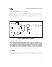
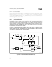
8.3.4 Mode 3 (Two 8-bit Timers)
Mode 3 configures timer 0 such that registers TL0 and TH0 operate as separate 8-bit timers (Fig-
ure 8-4). This mode is provided for applications requiring an additional 8-bit timer or counter.
TL0 uses the timer 0 control bits C/T0# and GATE0 in TMOD, and TR0 and TF0 in TCON in the
normal manner. TH0 is locked into a timer function (counting F
OSC
/12) and takes over use of the
timer 1 interrupt (TF1) and run control (TR1) bits. Thus, operation of timer 1 is restricted when
timer 0 is in mode 3. See section 8.4, “Timer 1,” and section 8.4.4, “Mode 3 (Halt).”
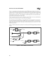
8.4 TIMER 1
Timer 1 functions as either a timer or event counter in three modes of operation. Figures 8-2 and
8-3 show the logical configuration for modes 0, 1, and 2. Timer 1’s mode 3 is a hold-count mode.
A4111-02
GATE
x
INT
x
#
TR
x
TL
x
(8 Bits)
TF
x
Interrupt
Request
12
T
x
Overflow
x
= 0 or 1
XTAL1
Reload
TH
x
(8 Bits)
C/Tx#
0
1