


8XC251SA, SB, SP, SQ USER’S MANUAL
A-104
Example: The accumulator contains 0C3H (11000011B) and R0 contains 55H (01010101B). After
executing the instruction
ORL A,R0
the accumulator contains 0D7H (11010111B).
When the destination is a directly addressed byte, the instruction can set combinations of
bits in any RAM location or hardware register. The pattern of bits to be set is determined by
a mask byte, which may be a constant data value in the instruction or a variable computed in
the accumulator at run time. After executing the instruction
ORL P1,#00110010B
sets bits 5, 4, and 1 of output Port 1.
Variations
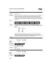
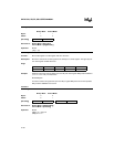
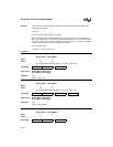
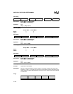
ORL dir8,A
Binary Mode Source Mode
Bytes: 22
States: 2† 2†
†If this instruction addresses a port (P
x
,
x
= 0–3), add 2 states.
Hex Code in: Binary Mode = [Encoding]
Source Mode = [Encoding]
Operation: ORL
(dir8) ← (dir8) V (A)
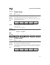
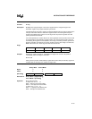
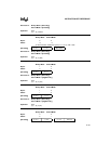
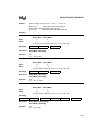
ORL dir8,#data
Binary Mode Source Mode
Bytes: 33
States: 3† 3†
†If this instruction addresses a port (P
x
,
x
= 0–3), add 1 state.
Hex Code in: Binary Mode = [Encoding]
Source Mode = [Encoding]
Operation: ORL
(dir8) ← (dir8) V #data
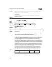
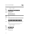
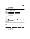
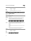
ORL A,#data
Binary Mode Source Mode
Bytes: 22
States: 11
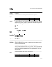
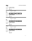
[Encoding] 0 1 0 0 0 0 1 0 direct addr
[Encoding] 0 1 0 0 0 0 1 1 direct addr immed. data
[Encoding] 0 1 0 0 0 1 0 0 immed. data