A-77
INSTRUCTION SET REFERENCE
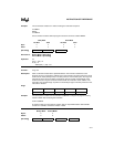
Example: The accumulator contains 01H. After executing the instruction sequence
JZ LABEL1
DEC A
JZ LABEL2
the accumulator contains 00H and program execution continues at label LABEL2.
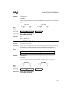
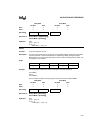
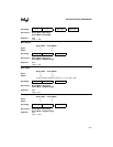
Binary Mode Source Mode
Not Taken Taken Not Taken Taken
Bytes: 22 22
States: 25 25
Hex Code in: Binary Mode = [Encoding]
Source Mode = [Encoding]
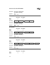
Operation: JZ
(PC) ← (PC) + 2
IF (A) = 0
THEN (PC) ← (PC) + rel
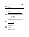
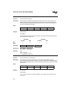
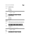
LCALL <dest>
Function: Long call
Description: Calls a subroutine located at the specified address. The instruction adds three to the
program counter to generate the address of the next instruction and then pushes the 16-bit
result onto the stack (low byte first). The stack pointer is incremented by two. The high and
low bytes of the PC are then loaded, respectively, with the second and third bytes of the
LCALL instruction. Program execution continues with the instruction at this address. The
subroutine may therefore begin anywhere in the 64-Kbyte region of memory where the next
instruction is located.
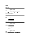
Flags:
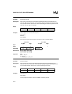
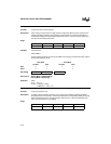
Example: The stack pointer contains 07H and the label "SUBRTN" is assigned to program memory
location 1234H. After executing the instruction
LCALL SUBRTN
at location 0123H, the stack pointer contains 09H, on-chip RAM locations 08H and 09H
contain 01H and 26H, and the PC contains 1234H.
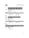
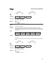
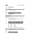
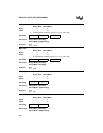
LCALL addr16
Binary Mode Source Mode
Bytes: 33
States: 99
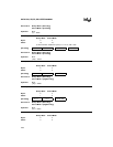
[Encoding] 0 1 1 0 0 0 0 0 rel. addr
CY AC OV N Z
—————
[Encoding] 0 0 0 1 0 0 1 0 addr15–addr8 addr7–addr0


