


8XC251SA, SB, SP, SQ USER’S MANUAL
A-52
Example: The accumulator contains 56H (01010110B), which represents the packed BCD digits of the
decimal number 56. Register 3 contains 67H (01100111B), which represents the packed
BCD digits of the decimal number 67. The CY flag is set. After executing the instruction
sequence
ADDC A,R3
DA A
the accumulator contains 0BEH (10111110) and the CY and AC flags are clear. The
Decimal Adjust instruction then alters the accumulator to the value 24H (00100100B),
indicating the packed BCD digits of the decimal number 24, the lower two digits of the
decimal sum of 56, 67, and the carry-in. The CY flag is set by the Decimal Adjust instruction,
indicating that a decimal overflow occurred. The true sum of 56, 67, and 1 is 124.
BCD variables can be incremented or decremented by adding 01H or 99H. If the
accumulator contains 30H (representing the digits of 30 decimal), then the instruction
sequence,
ADD A,#99H
DA A
leaves the CY flag set and 29H in the accumulator, since 30 + 99 = 129. The low byte of the
sum can be interpreted to mean 30 – 1 = 29.
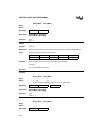
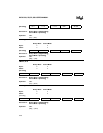
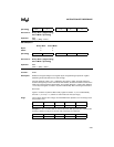
Binary Mode Source Mode
Bytes: 11
States: 11
Hex Code in: Binary Mode = [Encoding]
Source Mode = [Encoding]
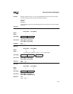
Operation: DA
(Contents of accumulator are BCD)
IF [[(A.3:0) > 9] V [(AC) = 1]]
THEN (A.3:0) ← (A.3:0) + 6
AND
IF [[(A.7:4) > 9] V [(CY) = 1]]
THEN (A.7:4) ← (A.7:4) + 6
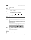
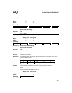
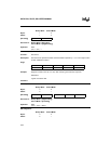
DEC byte
Function: Decrement
Description: Decrements the specified byte variable by 1. An original value of 00H underflows to 0FFH.
Four operands addressing modes are allowed: accumulator, register, direct, or register-
indirect.
Note: When this instruction is used to modify an output port, the value used as the original
port data is read from the output data latch, not the input pins.
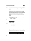
Flags:
[Encoding] 1 1 0 1 0 1 0 0
CY AC OV N Z
———✓✓