


A-35
INSTRUCTION SET REFERENCE
Example: Register 1 contains 0C3H (11000011B) and register 0 contains 55H (01010101B). After
executing the instruction
ANL R1,R0
register 1 contains 41H (01000001B).
When the destination is a directly addressed byte, this instruction clears combinations of bits
in any RAM location or hardware register. The mask byte determining the pattern of bits to
be cleared would either be an immediate constant contained in the instruction or a value
computed in the register or accumulator at run time. The instruction
ANL P1,#01110011B
clears bits 7, 3, and 2 of output port 1.
Variations
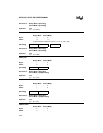
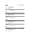
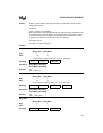
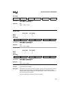
ANL dir8,A
Binary Mode Source Mode
Bytes: 22
States: 2† 2†
†If this instruction addresses a port (P
x
,
x
= 0–3), add 2 states.
Hex Code in: Binary Mode = [Encoding]
Source Mode = [Encoding]
Operation: ANL
(dir8) ← (dir8) Λ (A)
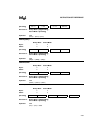
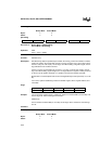
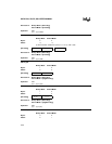
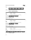
ANL dir8,#data
Binary Mode Source Mode
Bytes: 33
States: 3† 3†
†If this instruction addresses a port (P
x
,
x
= 0–3), add 1 state.
Hex Code in: Binary Mode = [Encoding]
Source Mode = [Encoding]
Operation: ANL
(dir8) ← (dir8) Λ #data
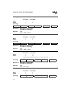
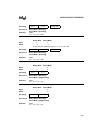
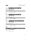
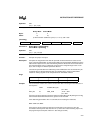
ANL A,#data
Binary Mode Source Mode
Bytes: 22
States: 11
[Encoding] 0 1 0 1 0 0 1 0 direct addr
[Encoding] 0 1 0 1 0 0 1 1 direct addr immed. data
[Encoding] 0 1 0 1 0 1 0 0 immed. data