Reference Manual
00809-0100-4665, Rev AA
August 2010
Rosemount 8732
6-10
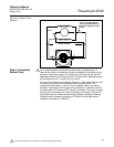
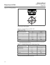
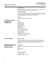
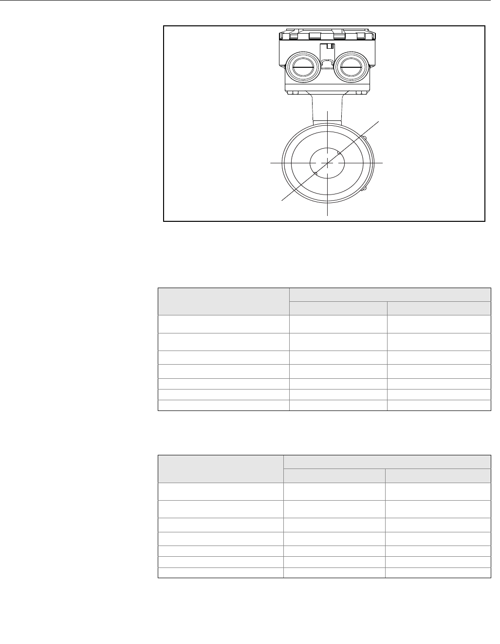
Figure 6-2. 45° Electrode Plane
To insure accuracy of resistance readings, zero out multimeter by shorting
and touching the leads together.
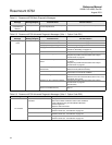
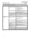
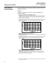
Table 6-6. Uninstalled Rosemount 8705 / 8707
Flanged Sensor Tests
Measuring at Connections
Hazardous Location Certifications
N0 N5, KD
18 and Electrode
(1)
(1) It is difficult to tell from visual inspection alone which electrode is wired to which number terminal in
the terminal block. Measure both electrodes. One electrode should result in an open reading, while
the other electrode should be less than 275 .
19 and Electrode
(1)
17 and Grounding Electrode
17 and Ground Symbol
17 and 18 Open Open
17 and 19 Open Open
17 and 1 Open Open
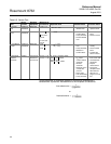
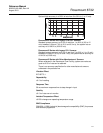
Table 6-7. Uninstalled Rosemount 8711 Wafer Sensor Tests
Measuring at Connections
Hazardous Location Certification
N0 N5, E5, CD
18 and Electrode
(1)
(1) Measure the electrode closest to the junction box
19 and Electrode
(2)
(2) Measure the electrode farthest away from the junction box.
17 and Grounding Electrode
17 and Grounding Symbol
17 and 18 Open Open
17 and 19 Open Open
17 and 1 Open Open
275
61k R75k
275
61k R75k
0.3
0.3
0.3
0.3
0.3
61k R75k
275
61k R75k
0.3
0.3
0.3
0.3


