


Reference Manual
00809-0100-4665, Rev AA
August 2010
5-11
Rosemount 8732
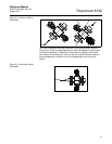
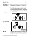
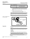
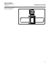
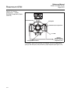
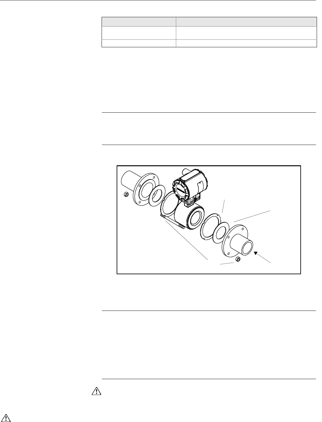
3. Place the sensor between the flanges. Make sure that the centering
rings are properly placed in the studs. The studs should be aligned
with the markings on the rings that correspond to the flange you are
using.
4. Insert the remaining studs, washers, and nuts.
5. Tighten to the torque specifications shown in Table 5-5. Do not
overtighten the bolts or the liner may be damaged.
NOTE
On the 4- and 6- inch PN 10-16, insert the sensor with rings first and then
insert the studs. The slots on this ring scenario are located on the inside of the
ring.
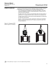
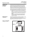
Figure 5-11. Gasket Placement
with Centering Rings
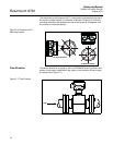
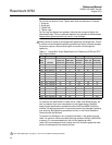
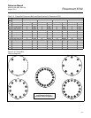
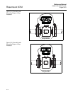
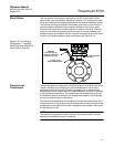
Flange Bolts Sensor sizes and torque values for both Class 150 and Class 300 flanges are
listed in Table 5-5. Tighten flange bolts in the incremental sequence, shown in
Figure 5-10.
NOTE
Do not bolt one side at a time. Tighten each side simultaneously. Example:
1. Snug left
2. Snug right
3. Tighten left
4. Tighten right
Do not snug and tighten the upstream side and then snug and tighten the
downstream side. Failure to alternate between the upstream and downstream
flanges when tightening bolts may result in liner damage.
Always check for leaks at the flanges after tightening the flange
bolts. All sensors require a second torquing 24 hours after initial flange bolt
tightening.
Table 5-4. Stud Specifications
Nominal Sensor Size Stud Specifications
0.15 – 1 inch (4 – 25 mm) 316 SST ASTM A193, Grade B8M
Class 1 threaded mounted studs
1
1
/2 – 8 inch (40 – 200 mm) CS, ASTM A193, Grade B7, threaded mounting studs
Customer-supplied
Gasket
FLOW
Installation, Studs
Nuts and Washers
Centering Rings
See ”Safety Messages” on pages 5-1 and 5-2 for complete warning information.