


Reference Manual
00809-0100-4665, Rev AA
August 2010
Rosemount 8732
2-10
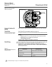
SENSOR CONNECTIONS This section covers the steps required to physically install the transmitter
including wiring and calibration.
Rosemount Sensors To connect the transmitter to a non-Rosemount sensor, refer to the
appropriate wiring diagram in “Universal Sensor Wiring Diagrams” on
page E-1. The calibration procedure listed is not required for use with
Rosemount sensors.
Transmitter to Sensor
Wiring
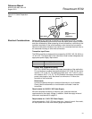
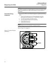
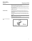
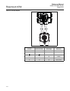
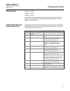
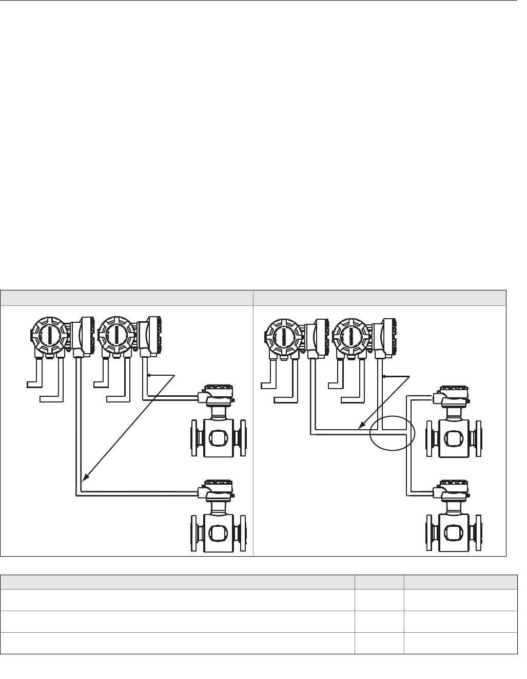
Flanged and wafer sensors have two conduit ports as shown in Figure 2-7.
Either one may be used for both the coil drive and electrode cables. Use the
stainless steel plug that is provided to seal the unused conduit port. Use
PTFE tape or thread sealant appropriate for the installation when sealing the
conduit.
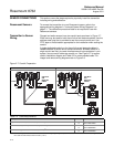
A single dedicated conduit run for the coil drive and electrode cables is
needed between a sensor and a remote transmitter. Bundled cables in a
single conduit are likely to create interference and noise problems in your
system. Use one set of cables per conduit run. See Figure 2-7 for proper
conduit installation diagram and Table 2-2 for recommended cable. For
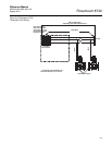
integral and remote wiring diagrams refer to Figure 2-9.
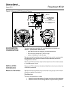
Figure 2-7. Conduit Preparation
Correct Incorrect
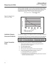
Table 2-2. Cable Requirements
Description Units Part Number
Signal Cable (20 AWG) Belden 8762, Alpha 2411 equivalent ft
m
08712-0061-0001
08712-0061-2003
Coil Drive Cable (14 AWG) Belden 8720, Alpha 2442 equivalent ft
m
08712-0060-0001
08712-0060-2003
Combination Signal and Coil Drive Cable (18 AWG)
(1)
(1) Combination signal and coil drive cable is not recommended for high-signal magmeter system. For remote mount installations, combination signal and coil
drive cable should be limited to less than 330 ft. (100 m).
ft
m
08712-0752-0001
08712-0752-2003
Coil Drive
and
Electrode
Cables
Power
Power
Outputs
Outputs
Coil Drive
and
Electrode
Cables
Power
Outputs
Power
Outputs