


Reference Manual
00809-0100-4665, Rev AA
August 2010
Rosemount 8732
6-6
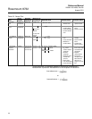
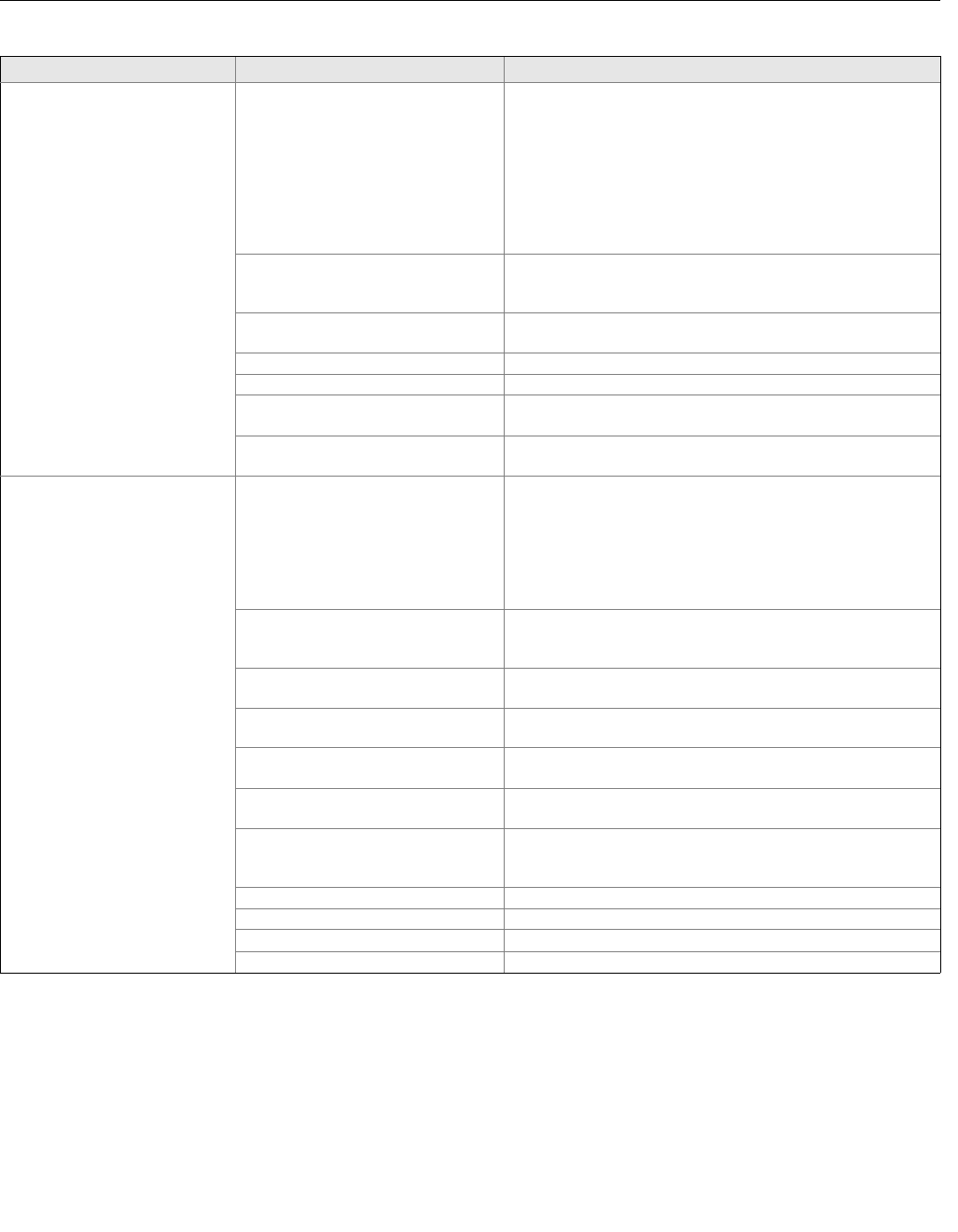
Meter output is unstable Medium to low conductivity fluids (10–
25 microsiemens/cm) combined with
cable vibration or 60 Hz interference
Eliminate cable vibration:
• Integral mount
• Move cable to lower vibration run
• Tie down cable mechanically
• Trim electrode and coil wires
• See “Conduit Cables” on page 2-6
• Route cable line away from other equipment
powered by 60 Hz
• Use 8712-0752-1,3 cable
Electrode incompatibility Check the Technical Data Sheet, Magnetic Flowmeter Material
Selection Guide (document number 00816-0100-3033), for
chemical compatibility with electrode material.
Improper grounding Check ground wiring – see “Mount the Transmitter” on page 2-3
for wiring and grounding procedures
High local magnetic or electric fields Move magnetic flowmeter (20–25 ft away is usually acceptable)
Control loop improperly tuned Check control loop tuning
Sticky valve (look for periodic
oscillation of meter output)
Service valve
Sensor failure Perform the sensor Tests A, B, C, and D
(See Table 6-5 on page 6-8)
Reading does not appear to be
within rated accuracy
Transmitter, control system, or other
receiving device not configured
properly
Check all configuration variables for the transmitter, sensor,
communicator, and/or control system
Check these other transmitter settings:
Sensor calibration number
Units
Line size
Electrode coating Use bulletnose electrodes in the Rosemount 8705 Sensor.
Downsize the sensor to increase the flow rate above 3 ft/s.
Periodically clean the sensor
Air in line Move the sensor to another location in the process line to
ensure that it is full under all conditions
Flow rate is below 1 ft/s
(specification issue)
See the accuracy specification for specific transmitter and
sensor
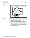
Insufficient upstream/downstream
pipe diameter
Move sensor to location where 5 pipe diameters upstream and 2
pipe diameters downstream is possible
Cables for multiple magmeters run
through same conduit
Run only one conduit cable between each sensor and
transmitter
Auto zero was not performed when the
coil drive frequency was changed from
5 Hz to 37.5 Hz
Perform the auto zero function with full pipe and no flow
Sensor failure—shorted electrode See Table 6-5 on page 6-8
Sensor failure—shorted or open coil See Table 6-5 on page 6-8
Transmitter failure Replace the electronics board
Transmitter wired to correct sensor Check wiring
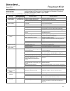
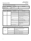
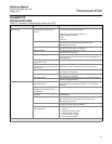
Table 6-4. Advanced Troubleshooting–Rosemount 8732
Symptom Potential Cause Corrective Action