


Reference Manual
00809-0100-4665, Rev AA
August 2010
Rosemount 8732
5-8
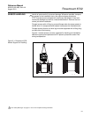
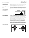
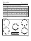
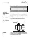
NOTE
Do not bolt one side at a time. Tighten each side simultaneously. Example:
1. Snug left
2. Snug right
3. Tighten left
4. Tighten right
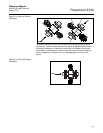
Do not snug and tighten the upstream side and then snug and tighten the
downstream side. Failure to alternate between the upstream and downstream
flanges when tightening bolts may result in liner damage.
Always check for leaks at the flanges after tightening the flange bolts. Failure
to use the correct flange bolt tightening methods can result in severe damage.
All sensors require a second torquing 24 hours after initial flange bolt
tightening.
For sensors with ANSI 600# full rated, 900#, 1500#, and 2500# flanges, the
liner is protected from over-compression by the flange design. Standard
flange torque specifications as determined by ANSI and ASME should be
followed. No special precaution is required to prevent liner damage caused by
over torquing. Bolt tightening procedures laid out in this Quick Installation
Guide must still be followed.
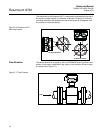
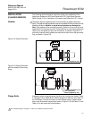
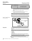
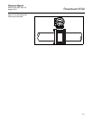
To prevent liner damage on any magnetic flowmeter, a flat gasket must be
used. For optimum results on meters with high pressure flanges (ANSI 600#
or above), it is recommended that a flat full face gasket be used.
Under NO circumstances should a spiral wound or flexitallic gasket be used
as this will damage the liner sealing surface.
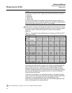
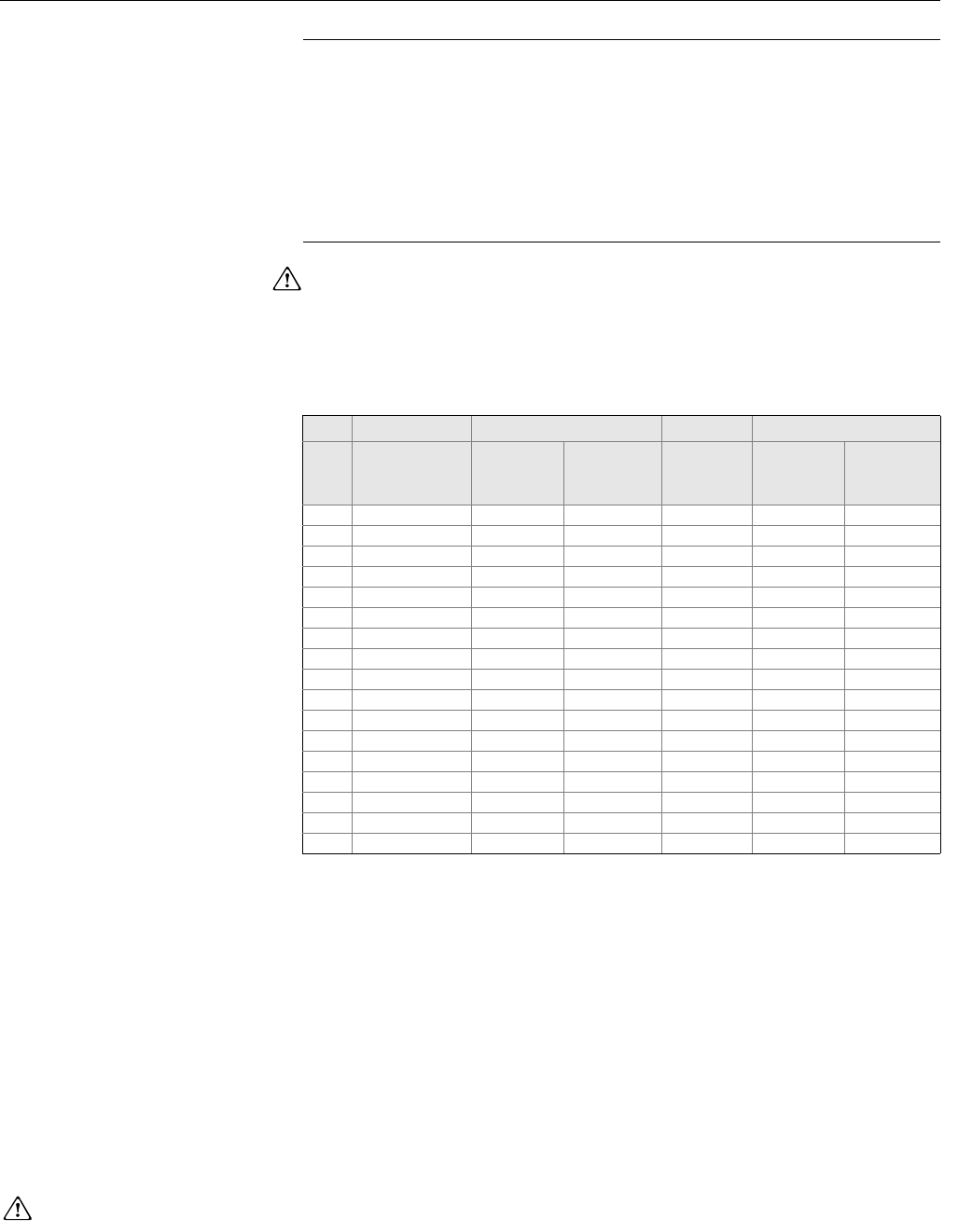
Table 5-1. Flange Bolt Torque Specifications for Rosemount 8705 and 8707
High-Signal Sensors
PTFE/ETFE liner Polyurethane liner
Size
Code
Line Size
Class 150
(pound-feet)
Class 300
(pound-feet)
Class 600
(1)
(Derated to
1000 psi)
(1) Derated available with PTFE lining only.
Class 150
(pound-feet)
Class 300
(pound-feet)
005 0.5-in. (15 mm) 8 8 8 8 -
010 1- in. (25 mm) 8 12 13 13 -
015 1.5-in. (40 mm) 13 25 29 29 7
020 2-in. (50 mm) 19 17 20 20 14
030 3-in. (80 mm) 34 35 41 41 23
040 4-in. (100 mm) 26 50 68 68 17
060 6-in. (150mm) 45 50 77 77 30
080 8-in. (200 mm) 60 82 121 121 42
100 10-in. (250 mm) 55 80 129 129 40
120 12-in. (300 mm) 65 125 146 146 55
140 14-in. (350 mm) 85 110 194 194 70
160 16-in. (400 mm) 85 160 274 274 65
180 18-in. (450 mm) 120 170 432 432 95
200 20-in. (500 mm) 110 175 444 444 90
240 24-in. (600 mm) 165 280 731 731 140
300 30-in. (750 mm) 195 375 - - 165
360 36-in. (900 mm) 280 575 - - 245
See ”Safety Messages” on pages 5-1 and 5-2 for complete warning information.