


Reference Manual
00809-0100-4665, Rev AA
August 2010
5-7
Rosemount 8732
INSTALLATION
(FLANGED SENSOR)
The following section should be used as a guide in the installation of the
flange-type Rosemount 8705 and Rosemount 8707 High-Signal Sensors.
Refer to page 5-10 for installation of the wafer-type Rosemount 8711 Sensor.
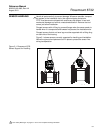
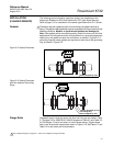
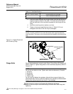
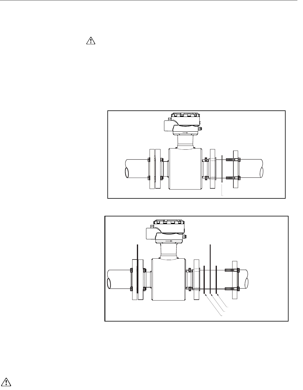
Gaskets The sensor requires a gasket at each of its connections to adjacent devices or
piping. The gasket material selected must be compatible with the process fluid and
operating conditions. Metallic or spiral-wound gaskets can damage the
liner. If the gaskets will be removed frequently, protect the liner ends. All other
applications (including sensors with lining protectors or a grounding electrode)
require only one gasket on each end connection, as shown in Figure 5-8. If
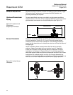
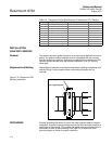
grounding rings are used, gaskets are required on each side of the grounding
ring, as shown in Figure 5-9.
Figure 5-8. Gasket Placement
Figure 5-9. Gasket Placement
with Non-attached Grounding
Rings
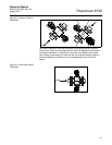
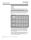
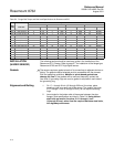
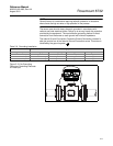
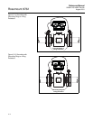
Flange Bolts Suggested torque values by sensor line size and liner type are listed in Table
5-1 on page 5-8 for ASME B16.5 (ANSI) flanges and Table 5-2 and Table 5-3
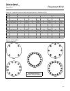
for DIN flanges. Consult the factory for other flange ratings. Tighten flange
bolts in the incremental sequence as shown in Figure 5-10. See Table 5-1 and
Table 5-2 for bolt sizes and hole diameters.
See ”Safety Messages” on pages 5-1 and 5-2 for complete warning information.
Gasket (Supplied by user)
Gasket (Supplied by user)
Grounding Ring
Gasket (Supplied by user)