Reference Manual
00809-0100-4665, Rev AA
August 2010
2-5
Rosemount 8732
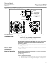
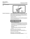
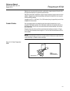
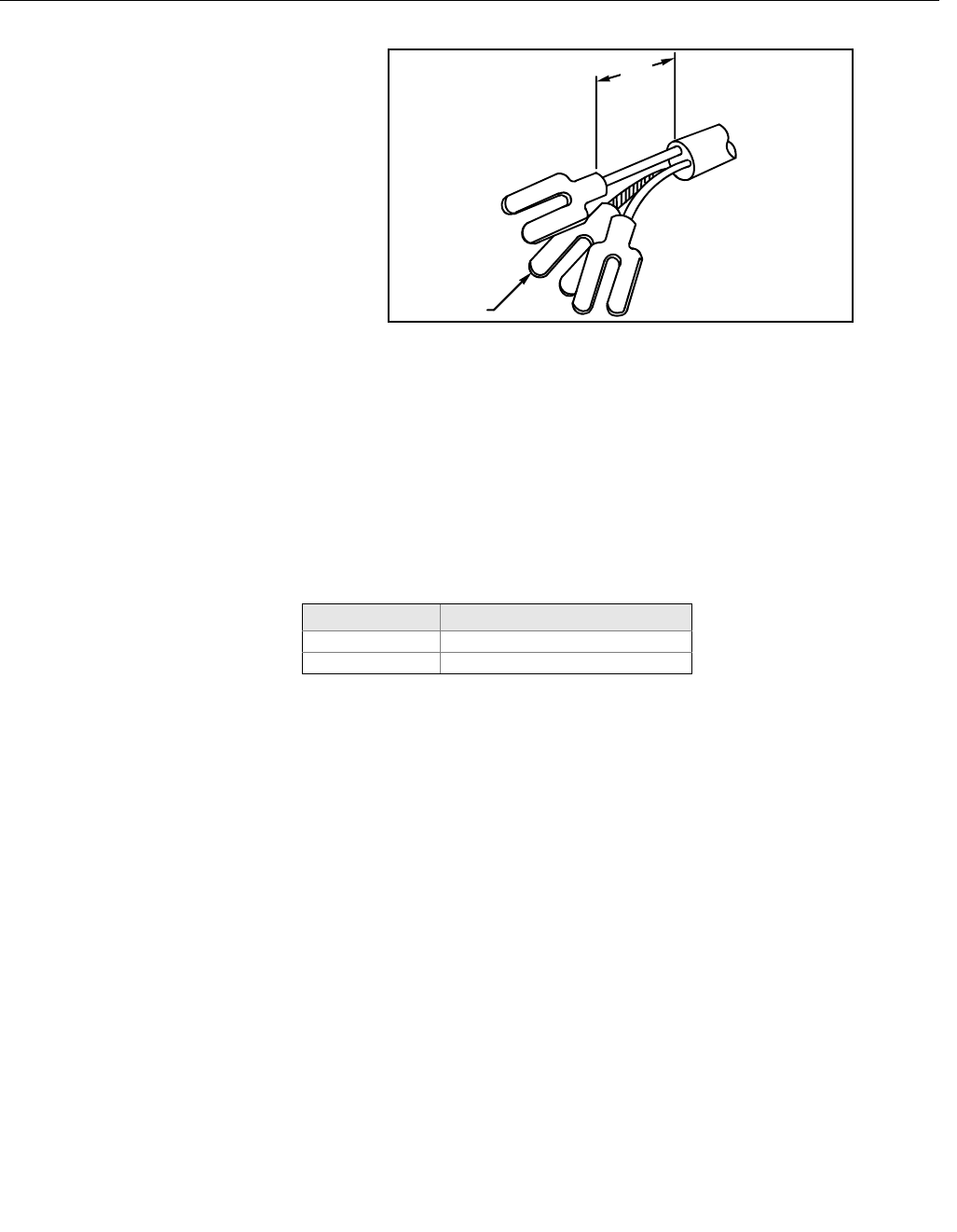
Figure 2-2. Cable Preparation
Detail
Electrical Considerations Before making any electrical connections to the Rosemount 8732, consider
the following standards and be sure to have the proper power supply, conduit,
and other accessories. When preparing all wire connections, remove only the
insulation required to fit the wire completely under the terminal connection.
Removal of excessive insulation may result in an unwanted electrical short to
the transmitter housing or other wire connections.
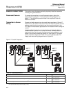
Transmitter Input Power
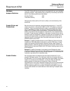
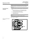
The 8732 transmitter is designed to be powered by 90-250 V AC, 50–60 Hz or
12–42 V DC. The eighth digit in the transmitter model number designates the
appropriate power supply requirement.
Supply Wire Temperature Rating
Use 14 to 18 AWG wire rated for the proper temperature of the application.
For connections in ambient temperatures above 140 °F (60 °C), use a wire
rated for 176 °F (80 °C). For ambients greater than 176 °F (80 °C), use a
wire rated for 230 °F (110 °C). For DC powered transmitters with extended
power cable lengths, verify that there is a minimum of 12 Vdc at the
terminals of the transmitter.
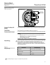
Disconnects
Connect the device through an external disconnect or circuit breaker.
Clearly label the disconnect or circuit breaker and locate it near the
transmitter.
Requirements for 90-250 V AC Power Supply
Wire the transmitter according to national, local, and plant electrical
requirements for the supply voltage. In addition, follow the supply wire and
disconnect requirements on page 2-6.
Requirements for 12-42 V DC Power Supply
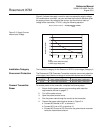
Units powered with 12-42 V DC may draw up to 1 amp of current. As a result,
the input power wire must meet certain gauge requirements.
NOTE
Dimensions are in
inches
(millimeters).
1.00
(26)
Cable Shield
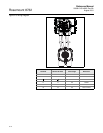
Model Number Power Supply Requirement
1 90-250 V AC
2 12-42 V DC


