Reference Manual
00809-0100-4665, Rev AA
August 2010
Rosemount 8732
6-8
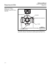
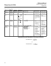
To test the sensor, a multimeter capable of measuring conductance in
nanosiemens is preferred. Nanosiemens is the reciprocal of resistance.
or
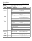
Table 6-5. Sensor Test
Test
Sensor
Location
Required
Equipment
Measuring at
Connections
Expected Value Potential Cause Corrective Action
A. Sensor
Coil
Installed or
Uninstalled
Multimeter 1 and 2 = R
• Open or
Shorted Coil
• Remove and
replace sensor
B. Shields to
Case
Installed or
Uninstalled
Multimeter 17 and
and case
ground
17 and case
ground
• Moisture in
terminal block
• Leaky electrode
• Process behind
liner
• Clean terminal
block
• Remove sensor
C. Coil Shield
to Coil
Installed or
Uninstalled
Multimeter 1 and
2 and
(< 1nS)
(< 1nS)
• Process behind
liner
• Leaky electrode
• Moisture in
terminal block
• Remove sensor
and dry
• Clean terminal
block
• Confirm with
sensor coil test
D. Electrode
Shield to
Electrode
Installed LCR (Set to
Resistance
and 120 Hz)
18 and 17 = R
1
19 and 17 = R
2
R
1
and R
2
should be stable
NO:
N5, E5, CD,
ED:
• Unstable R
1
or
R
2
values
confirm coated
electrode
• Shorted
electrode
• Electrode not in
contact with
process
• Empty Pipe
• Low conductivity
• Leaky electrode
• Remove coating
from sensor wall
• Use bulletnose
electrodes
• Repeat
measurement
• Pull sensor,
complete test in
Table 6-6 and
Table 6-7 on
page 6-10 out of
line.
2 R18
0.2
R
1
R–
2
300
R
1
R–
2
1500
1nanosiemens
1
1gigaohm
----------------------------=
1nanosiemens
1
110
9
ohm
-------------------------------=


