


Reference Manual
00809-0100-4665, Rev AA
August 2010
6-3
Rosemount 8732
DIAGNOSTIC
MESSAGES
Problems in the magnetic flowmeter system are usually indicated by incorrect
output readings from the system, error messages, or failed tests. Consider all
sources in identifying a problem in your system.
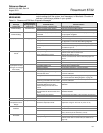
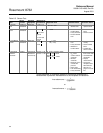
Table 6-1. Rosemount 8732 Basic Diagnostic Messages
Message
Local Display Error
Message (English)
Potential Cause Corrective Action
“Profibus Not
Communicating”
Profibus Not
Communicating
Profibus segment is disconnected Connect the Profibus segment
Profibus segment power missing Verify the segment Profibus voltage
Electronics failure Replace electronics
“Sensor Processor Not
Communicating”
Sensor Comm Err Transmitter input power (AC/DC) is not
connected
Connect the input power. If the LCD displays a message,
the input power is applied
Electronics failure Replace electronics
“Empty Pipe Detected” Empty Pipe Empty Pipe None - message will clear when pipe is full
Wiring Error Check that wiring matches appropriate wiring diagrams -
see Appendix E: Universal Sensor Wiring Diagrams
Electrode Error Perform sensor tests C and D (see Table 6-5 on page 6-8)
Conductivity less than 5 microsiemens
per cm
Increase Conductivity to greater than or equal to 5
microsiemens per cm
Intermittent Diagnostic Adjust tuning of Empty Pipe parameters
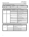
“Coil Drive Open
Circuit”
Coil Open Ckt Improper wiring Check coil drive wiring and sensor coils
Perform sensor test A - Sensor Coil
Other manufacturer’s sensor Change coil current to 75 mA
Perform a Universal Auto Trim to select the proper coil
current
Circuit Board Failure Replace Rosemount 8732 Electronics
Coil Circuit OPEN Fuse Return to factory for fuse replacement
“Auto Zero Failure
(Cycle power to clear
messages, no changes
were made)”
Auto Zero Fail Flow is not set to zero Force flow to zero, perform autozero
Unshielded cable in use Change wire to shielded cable
Moisture problems See moisture problems in “Accuracy Section”
Empty pipe is present Fill sensor with process fluid
“Universal Trim Failure” Univ Trim Fail No flow in pipe while performing
Universal Auto Trim
Establish a known flow in sensor, and perform Universal
Auto-Trim calibration
Wiring error Check that wiring matches appropriate wiring diagrams -
see “Universal Sensor Wiring Diagrams” on page E-1
Flow rate is changing in pipe while
performing Universal Auto-Trim routine
Establish a constant flow in sensor, and perform Universal
Auto-Trim calibration
Flow rate through sensor is
significantly different than value
entered during Universal Auto-Trim
routine
Verify flow in sensor and perform Universal Auto-Trim
calibration
Incorrect calibration number entered
into transmitter for Universal Auto-Trim
routine
Replace sensor calibration number with
1000005010000001
Wrong sensor size selected Correct sensor size setting - See “Line Size” on page 3-9
Sensor failure Perform sensor tests C and D (see Table 6-5 on page 6-8)
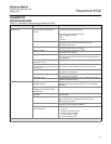
“Electronics Failure” Electronics Fail Electronics self check failure Replace Electronics
“Electronics
Temperature Out of
Range”
Temp Out of Rng Ambient temperature exceeded the
electronics temperature limits
Move transmitter to a location with an ambient
temperature range of -40 to 165 °F (-40 to 74 °C)
“Reverse Flow
Detected”
Reverse Flow Electrode or coil wires reverse Verify wiring between sensor and transmitter
Flow is reverse Turn ON Reverse Flow Enable to read flow
Sensor installed backwards Re-install sensor correctly, or switch either the electrode
wires (18 and 19) or the coil wires (1 and 2)
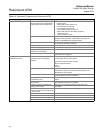
“Sensor Hi Limit
Exceeded”
Flow >Sens limit Flow rate is greater than 43 ft/sec Lower flow velocity, increase pipe diameter
Improper wiring Check coil drive wiring and sensor coils
Perform sensor test A - Sensor Coil (see Table 6-5 on
page 6-8)