Reference Manual
00809-0100-4665, Rev AA
August 2010
E-15
Rosemount 8732
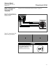
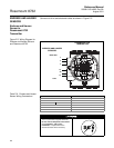
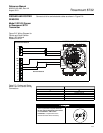
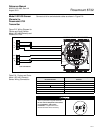
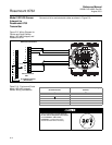
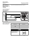
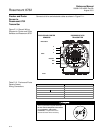
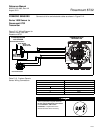
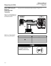
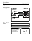
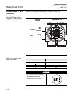
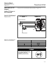
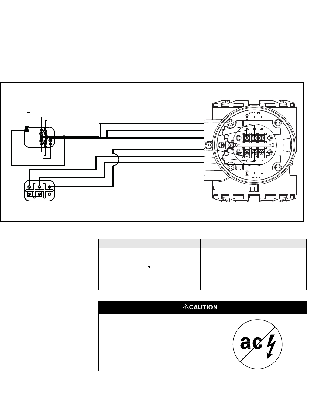
FOXBORO SENSORS Connect coil drive and electrode cables as shown in Figure E-12.
Series 1800 Sensor to
Rosemount 8732
Transmitter
Figure E-12. Wiring Diagram for
Foxboro Series 1800 and
Rosemount 8732
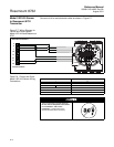
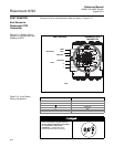
Table E-13. Foxboro Generic
Sensor Wiring Connections
ROSEMOUNT 8732
TRANSMITTER
Coil Connections
Electrode Connections
FOXBORO SERIES
1800 SENSOR
Outer Shield
White Lead
White Shield
Black Lead
Black Shield
Inner Shield
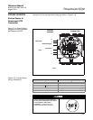
Rosemount 8732 Foxboro Series 1800 Sensors
1 L1
2 L2
Chassis Ground
17 Any Shield
18 Black
19 White
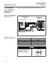
This is a pulsed DC magnetic flowmeter.
Do not connect AC power to the sensor
or to terminals 1 and 2 of the
transmitter, or replacement of the
electronics board will be necessary.


